Author:
Chris Glaser, Applications Engineer, Texas Instruments
Date
02/13/2013
 PDF
PDF
Click image to enlarge
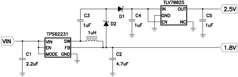
Figure 1: Low-cost power supply providing a regulated 1.8 V and 2.5 V using a step-down converter and auxiliary charge pump
In many low-power battery-powered applications, cost is king. If the cost to produce a device is above a certain threshold, determined by the device's functionality and the market, that device simply is not viable. Cost is an especially critical concern for certain medical devices such as thermometers and insulin pumps because these products require replacement at regular intervals to ensure accurate and reliable performance. Typically, the power supply required to power any device has a relatively significant associated cost. Some portable systems may require batteries only, but most require batteries and several power converters to transform the variable battery voltage into usable and regulated output voltages for the various circuits. Often, two different output voltages are required for the various circuitries in a given medical device. An alternative to using two separate power converters makes use of an auxiliary charge-pump circuit. The charge pump operates from the power converter's main output that provides the system's primary operating voltage, enabling a low-cost secondary output voltage in such systems. System description As an example of a typical battery-powered system, an insulin pump might require 200 mA at 1.8 V for a processor. At the same time, it may also need 5 mA at 2.5 V for sensitive analog circuitry, such as a voltage reference or sensor. Because the 1.8-V need is about 96.5% of the total output power, it dictates the battery type used, which in this case is two series-connected AA batteries. AA batteries are very low-cost and readily available, making it fast and easy for the diabetic to replace the batteries when needed without compromising the performance of this critical system. New AA batteries have a voltage range of approximately 1.6 V per cell, down to around 1 V per cell when depleted. The system's input voltage in this configuration is 3.2 V down to 2 V, which is well suited for a step-down converter providing 1.8 V. Such a step-down converter should be efficient to obtain a long battery life, integrated to reduce the number and associated cost of other necessary components, and low cost itself. For example, a step-down converter like the TPS62231 can provide up to 94% efficiency and only require three small and low-cost external components. Obtaining the 2.5-V voltage is more difficult, because the input voltage of 3.2 to 2 V varies both above and below the desired output voltage. A circuit that can step-up or step-down the input voltage is required, yet the functionality to both step-up and step-down clearly adds more cost. One further obstacle is the low noise required for powering a sensitive analog circuit in an insulin pump. Possible power converter topologies There are several different power converter topologies that meet the 2.5-V requirement, each with their own tradeoffs of cost, efficiency, and noise performance. Three examples are: 1. a buck-boost charge-pump converter running directly from the batteries, 2. a step-up converter running from the batteries followed by a linear regulator, and 3. an auxiliary charge pump circuit running from the step-down converter followed by a linear regulator. Buck-boost charge pump converter Implementing a separate regulated charge pump converter directly from the batteries is the most straightforward method. A buck-boost charge pump is required to step-down or step-up the battery voltage. This can vary above and below the 2.5-V output voltage as the battery discharges. For example, a charge pump like the REG710-25 requires only three external capacitors. While it is simple and integrated, it requires another semiconductor device, which increases the cost. Additionally, the efficiency at such low output currents is only around 50%, which shortens battery life. Finally, the noise performance of a charge pump may not be sufficient for the sensitive analog circuitry that it powers. This might cause inaccurate sensor readings or an imprecise reference voltage in the insulin pump, clearly affecting system performance. Additional output filters may be required, adding to the cost and complexity of the power converter. Step-up converter A second power converter topology employs both a step-up converter to boost the battery voltage to a constant level above the required 2.5 V, and a linear regulator to bring that voltage down to the desired level. Since most step-up converters are not designed to operate with input voltages above their output voltage, the step-up converter's output voltage should be set above the maximum battery voltage. This ensures that it never enters this operating condition. Setting the step-up converter's voltage at 3.3 V, for example, also gives the linear regulator plenty of headroom to reduce the voltage to 2.5 V. Headroom is the voltage differential between the input and output of a linear regulator and should be greater than 0.5 V for good noise performance. This headroom enhances the noise characteristics of the linear regulator and provides a very clean 2.5 V, perfectly suited for sensitive analog sensors or voltage references found in insulin pumps. An example of a low-cost step-up converter is the TLV61225, while an example of a low-cost linear regulator is the TLV70025. The example step-up converter has an efficiency of around 90% at the 5-mA operating point, while a linear regulator's efficiency is only 75% when converting 3.3 V to 2.5 V. Thus, the total efficiency of this topology is around 68%. The step-up converter, while highly integrated, requires two capacitors and an inductor; and the linear regulator requires two more capacitors. Combined with the two semiconductor devices, these other components present an efficient, high-performance, but expensive power converter. Auxiliary charge pump circuit A third power converter topology to provide 2.5 V uses an auxiliary charge pump operating from the main step-down converter, followed by a linear regulator to regulate the output voltage (figure 1). The step-down converter is configured as usual with the inductor, C1, and C2 providing the 1.8-V output at 200 mA. C3, D1, D2, and C4 form the auxiliary charge pump circuit, which produces VIN, plus the output voltage of 1.8 V, minus two diode drops across C4. Assuming diode drops of 0.3 V each, the output of this charge pump varies between 3.2 V and 4.4 V as the battery voltage varies. This is well suited to powering the linear regulator, allowing it the headroom necessary to clean up sufficiently the switching noise present on the charge pump's output. The only additional semiconductor device that this topology requires is a low-cost linear regulator. Linear regulators, due to their simplicity, cost much less than switching converters, such as charge pumps or step-up converters, and require fewer external components. The three additional capacitors and two diodes required by this auxiliary charge pump circuit are small and low-cost discrete components. The efficiency of the charge pump circuit is difficult to quantify because the step-down converter already provides the switching action and its losses are included in those that account for powering the 1.8-V rail. Assuming 80% efficiency for the C3, C4, D1, and D2 piece of the circuit and, assuming the linear regulator has on average a 3.8-V input, which yields an efficiency of 66%, the total efficiency to power the 2.5 V rail is about 53%.
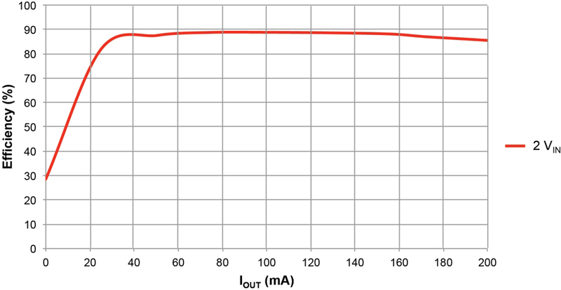
The measured efficiency of the total circuit, step-down converter plus auxiliary charge pump and linear regulator, running at the minimum input voltage of 2 V and 1-mA load on the 2.5-V output, is fairly constant at 88 percent (figure 2). System efficiency this high prolongs battery life. Furthermore, the linear regulator cleans up the switching noise of the auxiliary charge pump circuit, conditioning it to power the sensitive analog reference voltage or sensor. Of the three power-converter topologies we've examined, the auxiliary charge pump is the lowest cost and provides sufficient noise performance to power a sensitive analog circuit in an insulin pump. The efficiency of the auxiliary charge pump circuit by itself is theoretically poor, but considering that it only provides 3.5% of the total output power, it has a negligible impact on the system's battery life. Since it lacks intricate and relatively costly switching semiconductor devices and requires few external components, it is a viable low-cost power supply for cost-sensitive systems. Texas Instruments