Author:
Rudye McGlothlin, Marketing Director, Silicon Labs
Date
07/22/2019
 PDF
PDF
Click image to enlarge
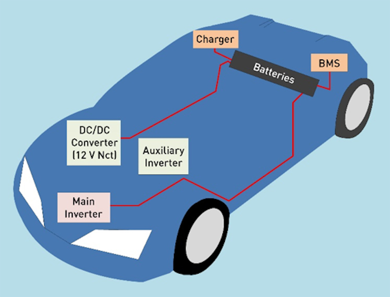
Figure 1. EV/HEV Major Electrical Assembly Locations
Electric and hybrid vehicles promise greater efficiency, reduced emissions, and eventual price and performance parity with gas-powered vehicles. To be competitive with existing vehicles, the batteries used in EV/HEVs must possess very high energy storage density, near zero self-leakage current, and the ability to charge in minutes instead of hours. In addition, the battery management and associated power conversion system must be of minimal size and weight and be able to deliver large amounts power to the electric motor efficiently.
EV/HEV battery management systems typically include five major circuit assemblies:
· On-board charger: Energy storage is provided by 400 V and greater lithium-Ion battery packs charged by an onboard charger (OBC) consisting of an ac-to-dc converter with power factor correction (PFC) and supervised by a battery management system (BMS). This charger accommodates a variety of external charge sources ranging from 110 V single-phase ac to 380 V three-phase ac.
· Battery management system: Battery cells are monitored and managed by the BMS to ensure high efficiency and safety. The BMS controls the charge, state of health, depth of discharge, and conditioning of individual battery cells.
· DC/DC converter: The dc/dc converter connects the high-voltage battery to the internal 12 V dc network, which also provides power to the accessories and bias to the local switching converters.
· Auxiliary inverter: Modern vehicles use belts to drive engine accessories, such as air conditioners and power steering pumps. EV/HEVs require the auxiliary inverter to generate the power necessary to drive these accessories electrically.
· Main Inverter: The main inverter drives the electric motor and it is also used for regenerative braking– returning unused energy to the battery.
Galvanic Isolation
Modular EV/HEV circuit assemblies have combinations of fixed and floating grounds, dissimilar voltages between modules, and local (and potentially lethal) battery and power supply voltages. Given these circumstances, galvanic isolation is a necessity in the design of electric and hybrid vehicles.
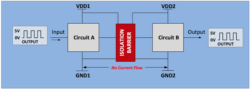
What is galvanic isolation, and what role does it play in electrical system design? Galvanic isolation insulates functional sections of electrical systems to prevent current flow between the sections while permitting information to be exchanged between the sections. Figure 2A demonstrates this concept with a simple isolated data exchange example between Circuits A and B. Dedicated bias supplies VDD1 and VDD2 provide 5 V power on their respective sides of the isolator. The 5 V ground-referenced pulse train applied to the Circuit A input is faithfully transferred to the isolator output with no current passing between GND1 and GND2 at any time during the transaction. In other words, the impedance between GND1 and GND2 effectively creates an open circuit, and yet a successful data transaction is completed between the two insulated circuits as stated in the galvanic isolation definition.
Click image to enlarge
Figure 2. Basic Isolator Behavior
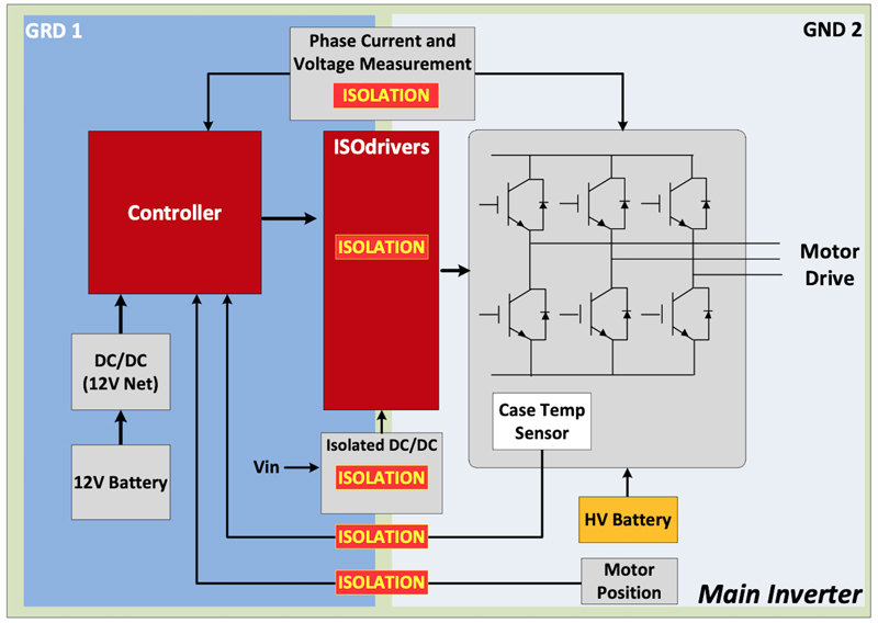
The benefits of digital isolation can be used in various combinations to make EV/HEV electrical systems safer and more reliable. The main inverter block diagram in Figure 3 shows where isolation is used. Isolation provides safety isolation, level shifting and voltage-level translation between the high-voltage motor drive and low-voltage controller in the phase current and voltage measurement circuits. Likewise, the isolated drivers provide these same functions between the driver and the high-voltage motor drive circuit. An isolated dc/dc converter uses linear safety isolation in the feedback loop to ensure that no current flows between the primary and secondary sides of the supply, eliminating the possibility of high-voltage breakdown or leakage to low-voltage circuits. Lastly, linear or digital isolators are used between sensors for safety, level shifting, voltage-level translation and possibly ground loop mitigation.
Click image to enlarge
Figure 3. Isolation in Main Inverter
Switch Mode Power in EV/HEVs
Switch mode power converters are an important part of EV/HEV systems and are used in the main and auxiliary inverters, the 12 V network dc/dc converter, and the battery charger. These converters transform voltage and current to meet the requirements of the devices they power and use isolation for safety and level shifting.
Figure 4 shows a block diagram of the battery charger’s internal ac-to-dc converter in which the input voltage is provided by external infrastructure, such as a charging spot. As shown, the charger’s ac input is immediately converted to dc by the input rectifier and filter and conditioned by the power factor correction (PFC) circuit. The conditioned dc voltage is then “chopped” into pulses by the primary-side switching circuit and applied to the transformer primary. The transformer “scales” the voltage and current pulses to meet the output requirements of the charger. Secondary-side circuits rectify and filter the high-frequency pulses, converting them into dc.
The power control supervises closed-loop operation and monitors the amount of power transferred to the battery until the battery is fully charged. Isolation components provide several important functions in this example: the transformer isolates power transfer between primary and secondary sides of the converter; the linear isolator provides safety isolation level shifting for the current sensor, high-voltage detection and the feedback control signal, and digital isolators provide safety isolation for the controller area network (CAN) bus interface.

Click image to enlarge
Figure 4. DC/DC (12 V Network) Converter
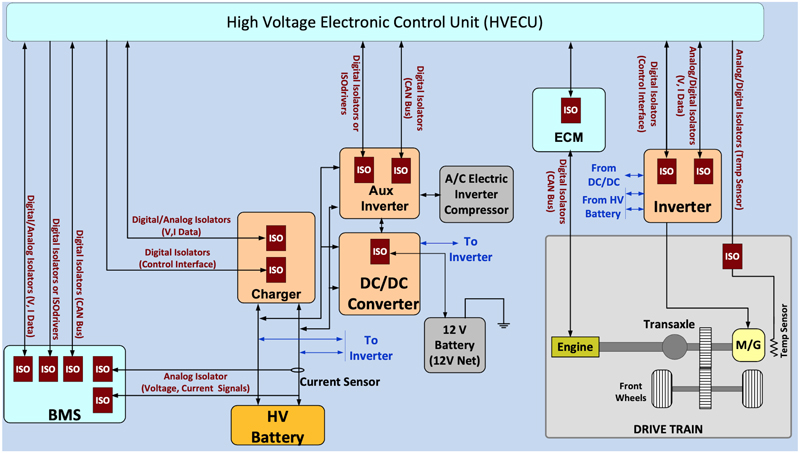
Figure 5 shows where and how isolation components are used in a simplified HEV system. HEVs present a more difficult technical challenge compared to EVs because of the added complexity of a small gas-powered engine in the drive train. This addition complicates both the mechanical drive train and electronics. Note that the gas engine in Figure 4 is managed by a dedicated engine control module (ECM), which includes an isolated CAN bus interface that enables the relatively lower voltage HV ECU to manage engine speed, timing and other key parameters. Note also that the motor/generator (M/G) temperature sensor isolation isolates the sensor ground from the HV ECU ground for safety and voltage level compatibility. In addition, the main and auxiliary inverters, charger and 12 V network dc/dc converters are all effectively isolated from one another wherever different ground potentials or high voltages are present.
Click image to enlarge
Figure 5. Simplified HEV Electrical System Block Diagram
Enhancing System Integration
Electric and hybrid vehicle designs must continue to reduce vehicle weight, improve battery technology, and increase power conversion system capabilities. These advancements in turn will require innovation in switched mode power topologies and larger scale, system-level ICs. While modern CMOS isolation devices offer gains in performance, the greatest benefit of digital isolation may be its ability to be integrated with other functions to form single-chip, isolated systems.
Isolation devices are ubiquitous in EV/HEV applications and are critical to the well-being of both the vehicle and the operator. These devices provide safety isolation, seamless level shifting, and eliminate ground noise; ultimately enhancing vehicle performance and reliability.
Silicon Labs