Author:
Ian Moulding, Marketing Manager, SBR Business Unit, Diodes Incorporated
Date
05/17/2013
 PDF
PDF
Click image to enlarge
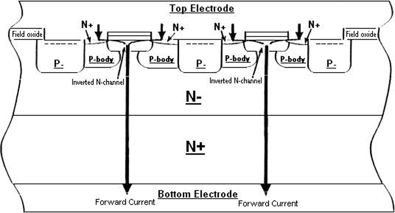
Figure 1. Forward operating mode of SBR structure
With their attractive low forward voltage drop and significant cost advantage, it's no surprise that Schottky diodes have become a defacto standard for AC bridge rectification in a myriad of different reference designs for MR16 LED lamp drivers. Problems include the extreme confines of a standard MR16 housing and the inhospitable environment from conducted heat dissipated by an LED cluster, where driver circuits are subject to ambient temperatures of up to 100C°. The weakest link If an LED lamp's going to fail it'll be down to the rectifier and here the standard Schottky offers up an inherent and well observed weakness. A device remains sensitive to changes in ambient temperature due to its high leakage current. Fact. Even for reasonably modest amount of applied heat, the Schottky's low energy metal barrier design makes it susceptible to destructive thermal runaway - when reverse power exceeds the diode's ability to expel heat at the rate at which it's generated. What makes the adoption of the Schottky all the more curious in this respect is that the importance of low leakage over and above that of a low forward voltage is well recognised. In an AC bridge rectifier each diode pair conducts for half a cycle and blocks for half a cycle. To minimise conduction losses, yes, a low forward voltage is a pre-requisite, but then in blocking mode, low leakage is paramount for minimising power losses. If the load was purely resistive then of course the duty cycle would be 50%, however since capacitors are often connected in order to reduce LED ripple current, then the conduction cycle of each diode can reduce to as little as 10%. As such, reverse leakage performance is in reality of primary importance, the forward voltage of secondary importance. Should we reconsider the merits of a PN junction diode perhaps? Well ‘no' is the simple answer to the question. Yes, a fast recovery epitaxial device (‘FRED') is certainly proven to exhibit far lower leakage at a higher temperature than the Schottky, but its forward voltage puts it at a distinct disadvantage. It is a source of higher power loss in the diode and greater heat generation, which is exactly what we're trying to avoid. So we continue to live with a compromise solution? Not necessarily. Think SBR The Super Barrier Rectifier (SBR®) is in reality nothing really new and has for sometime been successfully applied to improving the efficiency of higher power, high temperature power supplies. Combining the low forward voltage of characteristics of the Schottky with the low leakage attributes and stability of a PN junction diode, the SBR is however also a prime candidate for improving the reliability of MR16 LED lamps. For the uninitiated, the SBR structure is very similar to that of a MOSFET, but with the gate shorted, and employs thousands of individual cells to create a network of gate channels working in parallel. The structure incorporates an inverted gate that creates an inverted N-MOS channel directly under the cell. In forward operating mode, a large flow of electrons can move through the inverted N-channel with a reduced forward conduction loss. The current will flow from the top electrode, through the inverted N-channel, to the bottom electrode (Figure 1). In reverse operating mode, when applied voltage reaches a few hundred mVs, a pinch-off occurs due to the overlapping region in the depletion layers. As reverse voltage increases, the reverse leakage changes much slower and remains flat up to the breakdown voltage. This behaviour means the SBR does not suffer from the disadvantage of the Schottky. The SBR's forward conduction loss performance is also much better than that of a standard PN junction. In an input bridge application this advantage manifests itself as a significant power saving, which, with energy conservation in mind is not a factor to be ignored.
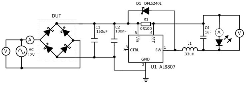
Put to the test In an evaluation circuit built around Diodes Incorporated's AL8807 LED Driver (Figure 2), the relative performances of the company's own DFLS240 2A 40V Schottky and SBR3U60P1 3A 60V SBR can be compared. The circuit is powered by a 12V AC supply and serves a single 1-Watt LED. The average continuous current through the bridge diodes is typically 300mA and the circuit is evaluated in ambient operating temperatures up to 1250C; selected as a ‘worst case' temperature used by MR16 lamp designers to assess product performance and reliability. Prior to real in-circuit evaluation, the suitability of the SBR or Schottky as a bridge diode in an MR16 LED lamp design can be assessed theoretically.
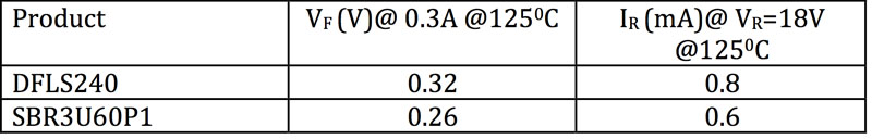
The typical forward conduction losses (VF) and reverse leakage losses (IR), under the stated conditions are specified by the typical Forward Voltage and Reverse Voltage characteristic curves of the respective datasheets, and are summarised in Table 1. The power loss that each leg of the diode bridge will generate under these conditions is calculated using the equation: PD = (VF * IL + ((1-D) * (VR * IR)) In which, PD = Power dissipated D = Duty cycle of between 0 and 1 VF= Forward voltage at IL @ 1250C IL = Maximum continuous current VR= Reverse voltage IR= Reverse leakage @ 1250C Substituting the parameters from Table 1 into the equation reveals that power dissipation losses for the DFLS240 are: PD = (VF * IL) + ((1-D) * (VR * IR)) PD = (0.32* 0.3)) + ((1-0.3) * (18 * 0.0008)) PD = 0.096 + 0.01 PD = 0.106W whereas for the SBR3U60P1 they are : PD = (VF * IL + ((1-D) * (VR * IR)) PD = (0.26 * 0.3) + ((1-0.3) * (18 * 0.0006)) PD = 0.078 + 0.00075 PD = 0.0885W The calculations already suggest then that the power dissipation of one leg of the diode bridge will be 16% lower when the SBR3U60P1 is used instead of the DFLS240. This lower power dissipation should result in the SBR operating at a far lower temperature in a real world test. It is worth noting that the actual in-circuit power dissipation would be doubled as two diodes conduct during each half cycle of the AC input.
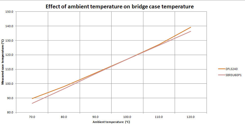
The evaluation board, with bridge populated first with the Schottky, then with the SBR, was placed in a temperature controlled chamber and ambient temperature increased incrementally to the maximum of 1250C. A thermal camera was used to measure the case temperature of Schottky and SBR at each increase in ambient temperature. The resulting data is shown graphically in Figure 3. As can be seen from the curves, at 1200C ambient, the case temperature (TC) of the SBR is 30C lower than the Schottky. Furthermore, as the junction temperature (TJ) of a diode is typically 80C higher than that of the case temperature then the junction temperature of the Schottky will be approximately 1470C. This is very close to its maximum rated junction temperature of 1500C and due to the low energy metal barrier of its design, there is a very real risk of thermal runaway. Taking into account the simple fact that for every 100C reduction in temperature, the reliability of an application doubles, then the significantly lower operating temperature of the SBR will therefore significantly improve high temperature reliability of MR16 designs. In summary, the lower forward voltage and reverse leakage of the SBR reduces power dissipation, enabling lower operating temperatures and a greatly reduced risk of thermal runaway. Clearly, the Super Barrier Rectifier provides a ready alternative for MR16 LED lamp applications. The economics of circuit design will for sure always have an important bearing, but if greater reliability and longer product life are the key design objective, then the price of challenging the status quo and making the change to an alternative high performance technology might prove a relatively small one to pay. Diodes Incorporated