Author:
Ann Starks, Applications Engineer, ON Semiconductor
Date
09/21/2012
 PDF
PDF
Competitive markets put pressure on OEMs to improve energy efficiency in their product designs. Accordingly, it is important to be able to monitor accurately currents through critical paths to support power-management and system-performance optimization. There are several different current-monitoring methods in current use. However, each of these common methods has distinct disadvantages. The need for a precision current-sense method has led to the creation of an integrated two-chip approach that provides accurate, ultra-low-loss current sensing with minimum affect to PCB layout and component count. Existing Current Sense Techniques The conventional current sensing method uses a precision sense resistor in the path of the subject current. A measurement of the voltage drop across the precision resistor allows a calculation of the current through the resistor. However, this method can incur significant power losses, especially at high currents. Other common current sensing techniques include the use of MOSFET RDS(on), inductor ESR, inductor voltage, or a current transformer. MOSFET RDS(on): Using the MOSFET on resistance eliminates the need for additional components, but the RDS(on) exhibits unit to unit variations, and the on-resistance value changes over temperature with up to a 35% difference in on-resistance from 27 to 100 °C. Inductor ESR: The inductor's ESR (equivalent series resistance) can sense the load current. A simple low-pass RC network filters the voltage across the inductor ESR. This method depends on known inductor characteristics to be effective, however. Inductor part-to-part variations can be as much as 20%. Inductor Voltage: This method measures the inductor voltage and calculates the current using Equation 1. The inductance can vary by 20% or more from part to part, limiting this method's accuracy.
Current Transformer: Most commonly used in high power systems, this method uses a current transformer to sense a fraction of the inductor current. This method is expensive to implement, however, and the transformer occupies considerable board space. SENSEFET current sensing The new ultra-low-loss measurement method uses a single MOSFET die, which features a small number of isolated source cells that connect to a separate sense pin, creating a matched internal mirror MOSFET. The ratio of source cells to sense cells is large. When current flows through the main MOSFET, a proportionally smaller current passes through this mirror MOSFET. The relationship between the two currents is IRATIO—the current ratio—and is defined in Equation 2. A typical IRATIO value is 400. The measurement circuit must hold the source and sense terminals at the same potential for the IRATIO to remain a known constant.
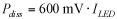
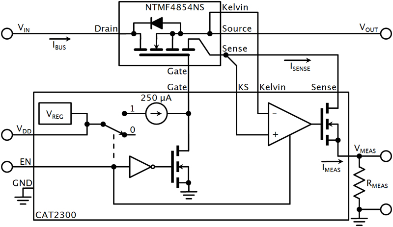
The main MOSFET and mirror MOSFET share common gate and drain connections, but have separate sources. A Kelvin connection to the main MOSFET source provides the means to monitor the source voltage without affecting its value. This single-die MOSFET allows for ultra-low-loss current monitoring by measuring the small current flowing through the mirror device. The measurement minimally affects system efficiency because it takes place outside the main current path: A typical value of ISENSE is 1/400th of ISOURCE. Accordingly, it's possible to measure the sense current and accurately calculate the load current. On Semiconductor calls its single-die mirror MOSFETs SENSEFETs. For example, one implementation of this precision, ultra-low-loss current-sensing method uses a SENSEFET and SENSEFET controller (Figure 1). The CAT2300 IC is a SENSEFET controller and current monitoring device for load switch applications. It can monitor load currents from 1 to 25 A for power supply rails ranging from 0.9 to 1.5 V. It serves the dual purpose of ultra-low-loss current sensing and controlling the SENSEFET's on-off state. The CAT2300's logic-level EN pin controls the SENSEFET gate. A logic-high or -low amplitude turns the SENSEFET on or off. Add a pull-up resistor between VDD and gate to speed the turn-on time. Alternatively, add a capacitance between gate and source to gain a softer turn-on. The current-sense circuit consists of an amplifier with a MOSFET follower stage. The Kelvin signal serves as a voltage reference, and the operational amplifier and follower stage accurately track the sense current by holding the Sense terminal at the same potential as the Kelvin terminal. An additional KS (Kelvin Sense) pin is included in the CAT2300 design as a connection for the mirror MOSFET source (the Sense pin), in order to eliminate any voltage drops in the PCB's sense trace.
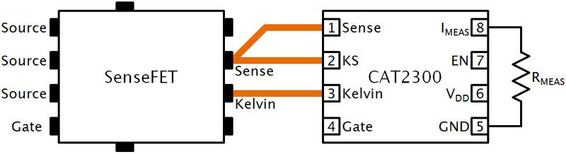
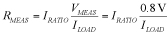
For a true Kelvin connection, the KS trace must be a dedicated connection, completely separate from the Sense trace and must begin directly at the Sense pin (Figure 2). Good layout practices are important to minimize loss in the PCB traces. Ideally, the layout design locates the CAT2300 as close to the SENSEFET as possible, keeping PCB trace lengths short and using proper Kelvin connections. On Semiconductor recommends a PCB with a separate ground plane. An external resistor, RMEAS, between the CAT2300's IMEAS pin and ground produces a scalable voltage that is proportional to the sense current flowing through the mirror MOSFET. VMEAS as a function of RMEAS is:
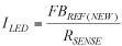
Combining equations 2 and 3 gives the load current:
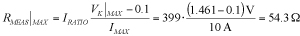
Measurement Resistor Selection The value of RMEAS depends on several factors, including the application's voltage rail and load current range. Equation 5 describes the maximum value for RMEAS in a given application. VK is the SENSEFET Kelvin terminal's voltage and IMAX is the application's maximum load current. The SENSEFET device's datasheet specifies IRATIO.
As an example, assume a circuit that uses the ON Semiconductor NTMFS4854NS SENSEFET in a 1.5-V power rail, with a maximum load of 10 A. You can estimate VK at maximum load current using the maximum RDS(on) value in the SENSEFET datasheet:
The NTMFS4854NS has a typical IRATIO of 399 and a maximum RDS(on) of 3.9 m? at VGS = 4.5 V. Using Equation 6: VK = 1.5 V ? (10 A)(3.9 m?) = 1.461 V. Therefore, the maximum voltage at the CAT2300's IMEAS pin is approximately 1.361 V at a 10-A load current. Calculate the maximum value of RMEAS by combining Equations 5 and 6:
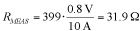
To get the best measurement results across the input voltage range, select a resistor value for RMEAS that produces 0.8 V on the CAT2300's ISENSE pin at the maximum load current:
To obtain 0.8 V on VMEAS at full load for this example, RMEAS becomes:
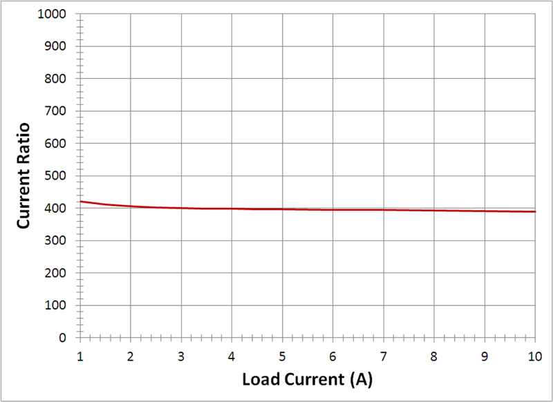
To obtain the best measurement accuracy, choose a resistor with a tolerance < 1%. Figure 3 illustrates measured IRATIO for a load switch application with a load current range of 1 - 10 A using the two-chip measurement circuit of Figure 1. As can be seen, the IRATIO is virtually flat across the load current range. The measured IRATIO loses accuracy for currents below 1 A due to the input offset voltage of the CAT2300's internal operational amplifier. The Source and Sense terminals operate at the same potential to have a constant IRATIO. The input offset voltage of the operational amplifier creates a voltage difference between the two terminals, introducing measurement error that is most prominent for currents below 1 A. On Semiconductor