Author:
Trevor J. Smith, Technical Marketing Manager, Tektronix
Date
02/13/2013
 PDF
PDF
Click image to enlarge
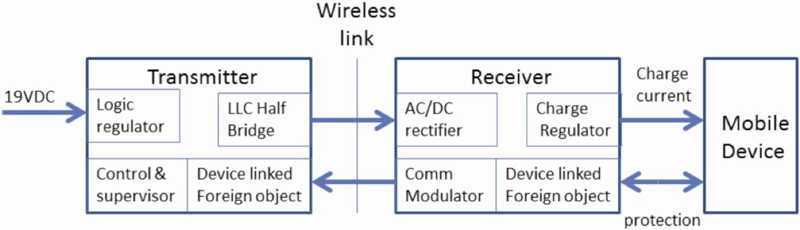
Figure 1: Qi wireless-charging system simplified block diagram
Mobile electronics can be found everywhere—homes, hospitals, schools, purses, and pockets. With the explosion in portability, consumers have come to expect and demand long battery life. Energy-efficient design techniques and improved battery technologies have helped to extend battery life but recharging devices is still a necessary and sometimes burdensome task. Wireless-power charging systems look to simplify portable-electronics recharging by transmitting energy to the device without a physical connection. There are various implementations and standards for wireless charging but most use some form of electromagnetic induction. One example is the Qi (pronounced chee) interface as developed by the WPC (Wireless Power Consortium). Unlike wireless-telecommunication systems like radio or cellular phones, wireless-power transmission depends more on the efficiency of transfer than signal to noise ratio. From a measurement perspective, the chargers present many challenges to the designer. The Qi wireless charger produces 5 W of charging power, while the Energy Star goals require high operating efficiency and low standby power. The efficiency of power transfer is dependent on system design including the transmitter, the receiver, and the interactions between them. Designs typically target greater than 70% efficiency for a 5-W system. The selection of coils, shielding, components, and physical design influence the overall system efficiency This is more complicated in a wireless charging system than in a typical charger, because the wireless system requires both a transmitter and a receiver. Other complications exist due to the shielding requirements—necessary to protect sensitive electronics and the battery from the RF fields—and foreign-object detection to prevent heating of nearby metal objects. System Overview While both interesting and challenging, the Qi system includes low frequency modulated RF, digital, and analog circuits all on a single board (figure 1). The charging system uses digital communication, both for JTAG debugging and for transferring data between the secondary and primary circuits across the resonant link. A secondary-side microcontroller monitors the charger's output voltage, generates signals, and uses modulation techniques to transfer information to the primary side. The primary-side microcontroller demodulates and interprets the information. The standard calls for organizing the modulated information into information packets comprising preamble bytes, header bytes, message bytes, and checksum bytes. Per the WPC specification, information packets can relate identification, configuration, control-error, rectified-power, charge-status, and end-of-power-transfer information.
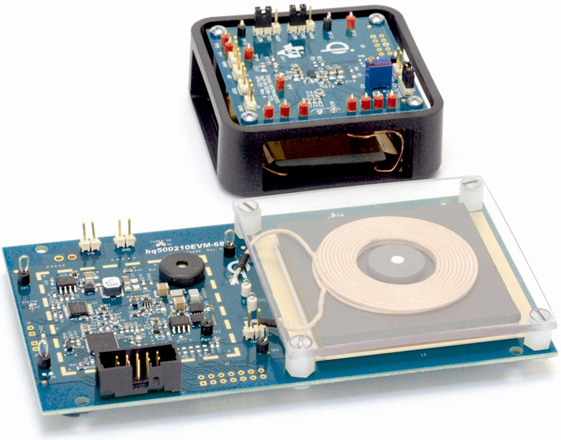
Setting Up the Measurement For this example, we tested a Texas Instrument wireless-power set, including a Bq500210EVM-689 transmitter and Bq51013EVM-725 receiver (figure 2). In addition to transferring power, the transmitter and receiver system also communicates controls signals modulated on top of the RF power signal from the secondary to the primary. The communication link allows the system to dynamically monitor and control power levels to prevent overheating due to nearby metal objects.
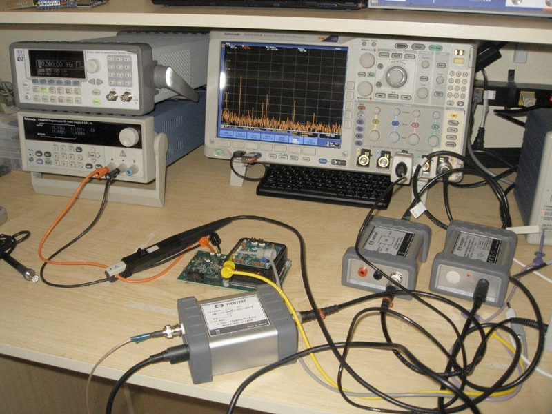
For the test setup, a Tektronix PWS4323 programmable power supply provides the necessary 19-V and 500-mA DC input power (figure 3). The MDO4104-6 MDO (mixed-domain oscilloscope) makes the measurements. This instrument provides 1 GHz bandwidth across four analog channels and includes serial packet decode for many industry standard control buses such as I2C and SPI. The MDO4104-6 includes an RF input to measure the RF signals up to 6 GHz. The MDO monitored control signals via the analog input and the RF signal and analyzed their respective harmonics with the RF input channel. Note, due to the planar coupling and close proximity of the primary and secondary coils it is difficult to measure the energy transfer wirelessly. Consequently, we monitored the power on the secondary side with a high impedance voltage probe directly at the output. The Qi charger's power stage is based on a half-bridge LLC topology resonant converter controlled directly from the primary-side charger controller. The resonant converter is frequency modulated over a range of approximately 110 to 205 kHz, as required by the WPC standard, to regulate the charger output power.
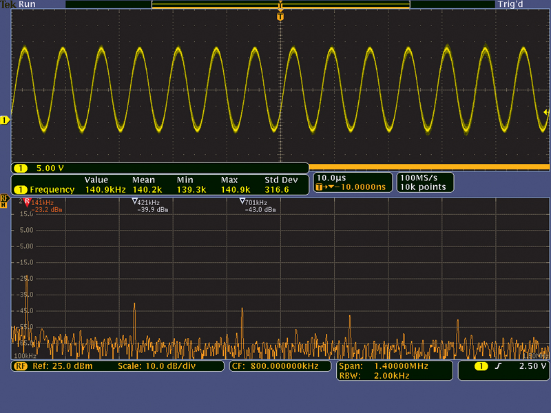
There are several ways to look at the LLC resonant waveforms. Figure 4a shows a facsimile of the resonant-link current, measured with a voltage probe connected to the resonant capacitor link at TP2 and also shows the resonant frequency. This current is also measureable directly using a current probe or by means of the I_Sense testpoint on the transmitter board. The RF power signal on the transmitter side is measureable with a voltage probe connected to TP1 via a Picotest J2180A preamplifier. The preamplifier provides a high input impedance and a 50 ? output impedance, facilitating a voltage probe connection to the LLC half-bridge switch node.
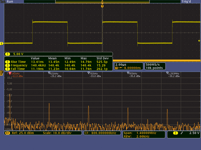
The RF channel displays the fundamental operating frequency of 141 kHz and is also rich with the odd harmonics associated with the 50% duty cycle switch voltage. The lack of even harmonics provides assurance that the duty cycle is precisely 50% (figure 4b).
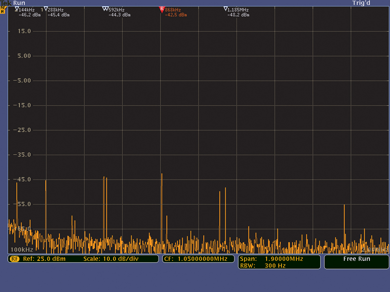
The MDO also measures higher frequency signals, such as EMI. Figure 5a shows the radiated EMI over a frequency range of 100 kHz to 2 MHz from the LLC half bridge switching, as well as from a low power 600 kHz buck regulator that efficiently converts the 19-V DC input voltage to 3.3 V required by the transmitter controller. Figure 5b shows the radiated EMI signals from the LLC half bridge switches, 600-kHz buck regulator, and 31-MHz microcontroller over a frequency range of 5 to 50 MHz.
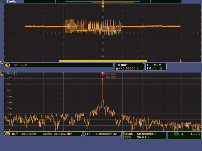
The digital communications across the resonant link implement using either resistive or capacitive techniques. Either method results in an amplitude modulation of the primary voltage. An MDO4000's spectrum-time capabilities show the time-varying nature of the modulation behaviour, specifically with the amplitude vs. time waveform (figure 6). The upper trace shows the amplitude modulation signal while the lower half shows the resonant link signal in the spectrum view. The MDO can extract the digital information using either a voltage probe or a near-field H probe, connected to the RF input via the Picotest J2180A preamplifier. This set up uses a near-field probe set from Electro-Metrics.

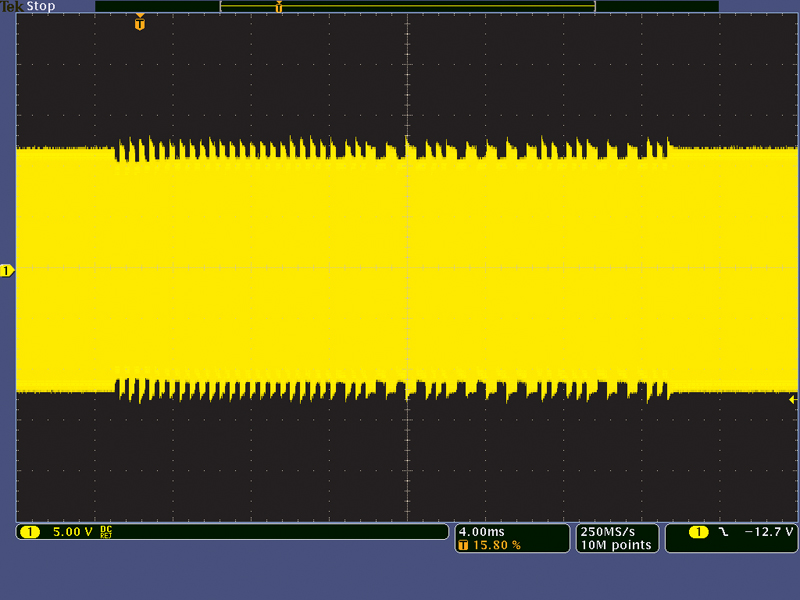
The MDO can also display the communication signals in the time domain on the receiver modulation-control pin and transmitter-primary winding voltage (figure 7). Both of these signal measurements use a TDP0500 differential voltage probe for maximum clarity and minimum circuit loading. The differential probe is more important in the measurement of the primary voltage than it is for the receiver controller voltage. This is due to the receiver control signal being ground-referenced and of relatively low impedance. The primary voltage is floating and, being part of the resonant tank circuit, the primary voltage is more sensitive to loads such as the input capacitance of voltage probes. The Qi charger ultimately provides a 5-V 1-A output to charge portable electronic devices' batteries. The LLC half-bridge converter coarsely regulates the secondary side voltage. A 5-V LDO precisely regulates the output.
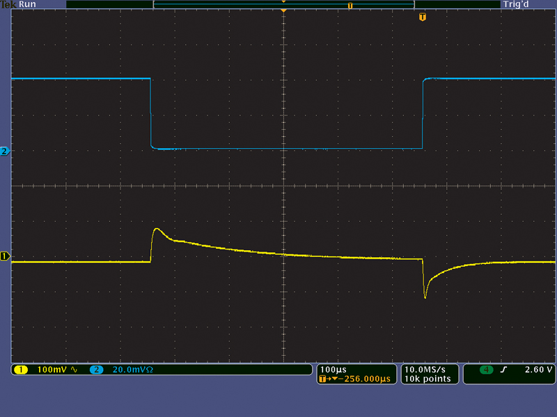
A small-signal step load current applied to the 5-V output, using a Picotest J2111A current injector, serves as the stimulus to measure the dynamic response and control loop stability of this final output regulator (figure 8). The current injector is in place of an electronic load to allow faster rise and fall times. The primary value of a mixed-domain oscilloscope is its ability to make time-correlated measurements across two domains: time and frequency. In addition, it can make these measurements between multiple analog, digital, and RF signals. Time-correlated measurements allow the mixed-domain oscilloscope to measure timing relationships between all of its inputs. It can measure, for instance, the time between a control signal and the beginning of a radio transmission, the rise time of a transmitted radio signal, or the time between symbols in a wireless data stream. The MDO can analyze a power-supply-voltage dip during a device state change and correlate it to the impact on the RF signal. Time correlation is critical for understanding the complete system operation: cause and effect. Using the MDO4000 we were able to measure the logic, RF, and analog functions of the Qi wireless battery charger, aided by a few probes and accessories. In the case of the communication signal, the MDO measured the signals in more than one domain. This included monitoring control signals, RF received output with spectrum and time-domain views. This capability allowed us to see the signal at its point of origin, within the RF link signal, and at the point of receipt across the transmitter winding. We also measured the performance of the final LDO output regulator and captured the EMI signals. Tektronix