Author:
Danielle Sklepik, BEAR Power Supplies
Date
04/04/2014
 PDF
PDF
Operating rooms and clinical settings are crowded with instruments that pack in more functions and features every year, such as surgical tools with lights, lasers and video microscopes. The pressure for them to be smaller, lighter and easy to move around continues to grow. Since the AC-DC converter is often the largest component in an instrument, this pressure lands heavily on the power supply designer.
The drive to minimize the size of the power supply conflicts with the imperative for reliability. This leads to some interesting challenges in specification development, component selection and board layout.
Many medical equipment OEMs market and sell their products worldwide. Rather than create different versions for different regions, they require the AC/DC converters to accept a universal input voltage, that is, 90-264VAC. This AC input is rectified to a DC voltage of 127-373V using the formula
V = Vrms √2
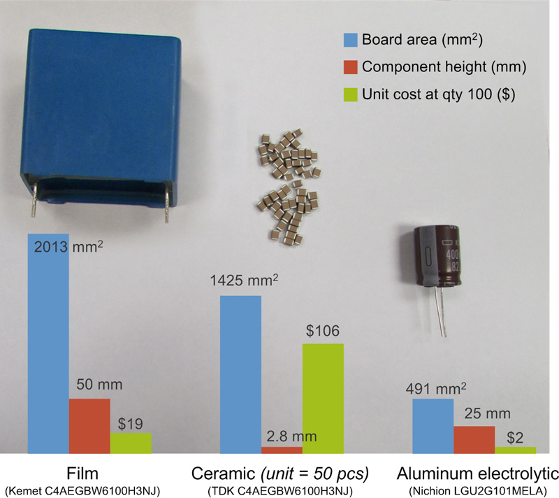
which means the rectifier circuit requires capacitors that are rated for more than 373V. A full-wave rectifier circuit will typically need 100µF to 400µF of capacitance, which makes aluminum electrolytic capacitors the only real choice due to cost and size (see Figure 1).
Click image to enlarge
Figure 1: Component height, board space and cost for 100 µF of capacitance with common capacitor types, rated for more than 373 V.
Specifically:
-A 100µF aluminum electrolytic capacitor rated for 400V is available in a 25mm dia. x 25mm tall through-hole package, costing $2 to $5.
-Ceramic capacitors rated for 450V are available, but the maximum capacitance is 2.2µF. You would need to use 50 of them to get 100µF, for a cost of $50 to $100.
-A 100µF film capacitor rated for 400V costs about $20 and measures a whopping 56 x 33 x 49 mm.
Compensating for the drawbacks of aluminum electrolytics
The requirement to use aluminum electrolytic capacitors means that the capacitors will be the life-limiting component of a medical power supply. These capacitors contain a liquid electrolyte that dries up over time, even sitting on the shelf. Wear-out is the most common failure mode, with gradual conversion to an open circuit as the device becomes increasingly resistive.
There are a several things a power supply designer can do to compensate for this and create a reliable, long-life and compact power supply. The most obvious is to choose a capacitor with the longest rated lifetime. “Long life grade” capacitors come with lifetime ratings as high as 12K hours, but those rated for 400V give you only a few nanoFarads in very large packages, so we usually have to settle for 2K to 4K hours.
Next, you can choose a capacitor that has a higher temperature rating and a higher ripple current rating than you think you will need. A component rated for 85 °C may seem sufficient for the hospital environment, where the worst-case specification is typically 0°C to 60°C, but a capacitor rated for 105°C will have a longer life at the same temperature. It will also be larger, and more expensive.
Likewise, a capacitor with a 2A ripple current rating will last longer than one with a 1A rating, even if you expect less than 1A ripple current.
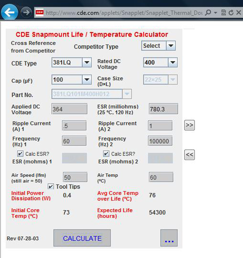
With these choices, you can significantly increase the expected life of a capacitor. Using one online calculator (see Figure 2) shows that a selected capacitor rated for 2K hour life at 105 °C and 1 A ripple current will have an actual expected life of more than 54K hours when used at the lower 60 °C and 0.5 A ripple current.
Here, a 100µF / 400 V capacitor rated for 2K hours at 105°C and 1A ripple current is shown to have an actual expected life of >54K hours when used at a lower temperature (60°C) and ripple current (0.5 A), with applied voltage of 364 V DC.
Click image to enlarge
Figure 2: An online calculator shows the effect of ripple current and temperature on capacitor expected life.
Other ways to maximize MTBF
Another approach to maximizing power supply MTBF is to over-spec the power requirement. It was once common to specify a 100W supply when 50W was needed for the application, in the effort to increase the usable life of the converter as the capacitors aged and the power dropped below the 100W specification. Among the drawbacks of this approach is that converters of 75W or more require power factor correction, increasing the board size and cost.
Today’s components have improved and this technique is no longer needed. It’s better to specify a 50 W supply for a 50 W application, as long as you make sure to consider the tolerances of all components, not only when they are new but also at the end of the power supply’s intended lifetime.
For example, stacking up the tolerances of all components including the capacitors, transformer, and ICs, you may conclude that designing for an initial low-end input of 86 VAC would be acceptable for a universal input spec of 90-256VAC. However, considering the tolerances of all the components at the target MTBF of the power supply gives a different result. At BEAR Power Supplies, after considering the tolerance stack-up and adding a safety margin, we typically design to something closer to 80VAC for the low-end input of medical AC/DC converters at their end of life. This is typically 5000 to 7500 hours, which may be four hours a day for five years for instruments such as surgical tools, or 12 hours a day for two years for products like infusion pumps.
Fitting capacitors into limited space
Fitting the capacitors into the smallest board space is the next challenge. Choosing taller, smaller-diameter packages is usually best. However, we often have a 30 mm height constraint on the complete assembly, so we are limited to the 25 mm tall aluminum electrolytics and need to use several of them to get enough capacitance.
Leakage current and capacitance
Next you need to consider the constraints on the leakage current for patient safety. This is the current that flows from the primary to the secondary of the power supply unit. IEC standard 60601-1 revision 3 specifies the maximum leakage current for medical power supplies, depending on the type of medical use. A CF-rated device is one which may come into internal contact with a patient, such as a surgical tool. A BF-rated device is one which may come into contact with a patient’s skin. Because the skin provides some protection against a leakage current, the limit is higher. The leakage current will be determined by the capacitance between the primary and secondary, and translates to a maximum capacitance of 92 pF for universal input CF-rated supplies.
If the device will be used in an operating room, you may need to meet even lower capacitance specs to withstand the application of a defibrillator. When the high voltage of the defibrillator is applied across the heart, any instrument that may potentially remain in contact with the patient must not provide a path to ground through the power supply, which would render the defibrillator ineffective and cause serious injury at the point of contact with the instrument. We have designed power supplies with capacitance between input and output lower than 30 pF for this purpose.
When calculating the capacitance, you must include the inherent capacitance between the primary and secondary windings. With traditional winding techniques, this is typically 100 - 200pF for converters between 50W and 250W, which is higher than the CF limit, so you need to use creative winding techniques.
Capacitors and EMI
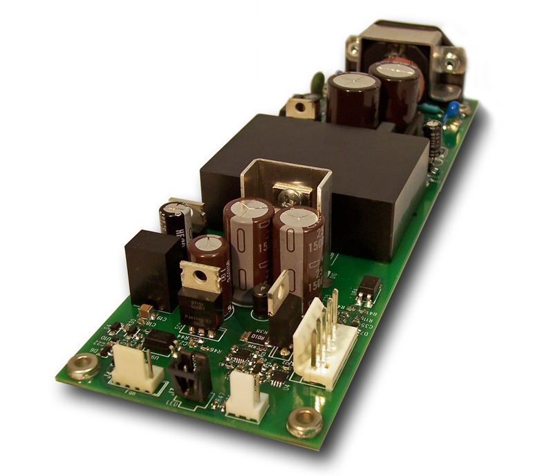
Another common design technique is to add a Y1 capacitor, typically around 2.2 nF, between the primary and secondary to reduce EMI. While this is a simple solution for EMI, it will result in too much leakage current to meet the IEC 60601-1 requirement. You will have to carefully consider the board layout and look for other ways to mitigate all sources of EMI. Experienced power supply designers have developed a number of innovative isolation techniques and create custom medical power supplies of more than 600 W with leakage current less than 5 μA (see Figure 3).
Click image to enlarge
Figure 3: Custom 75 W dual-output AC/DC medical power supply has a CF-rated output with capacitance of less than 15 pF.
Capacitor choice is a key aspect of medical power supply design. With experience and careful consideration, you can maximize MTBF, minimize board size, and meet patient safety requirements. The CF-rated output can be switched off, leaving a separate BF-rated output active to power electronics used in the vicinity of a patient. (BEAR Power Supplies)