Author:
Guillemette Paour, Global Market Manager, Automotive, Tyco Electronics Circuit Protection Devices
Date
01/15/2011
 PDF
PDF
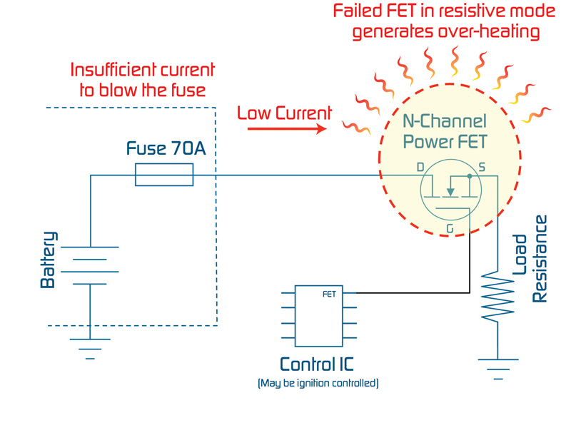
The growing demand for electronics that can operate in harsh environments such as under-hood automotive systems and rugged industrial applications is fueling a trend toward new materials and more efficient power components. High-power, high-temperature applications place greater demands on power electronic systems, resulting in the potential for serious thermal issues when components such as power Field Effect Transistors (powerFETs), capacitors, resistors or integrated circuits (ICs) fail due to long-term exposure to harsh environments. Improving power component performance, using design techniques that spread heat more evenly, and incorporating new heat sink materials are some of the solutions that have been proposed to enhance thermal management. Nevertheless, many designers currently rely on secondary protection to help stop thermal runaway events that can be generated by power component failures or corrosion-induced heating. The most common approach is to use a thermal fuse/Thermal Cut Off (TCO) or a thermal switch. These devices both offer the designer wide and specific temperature activation characteristics in both AC and DC applications, but they present challenges in the board assembly process. Because more and more printed circuit boards (PCBs) utilize only surface mount components, using a through-hole device can translate to special mounting procedures and additional cost and complexity. Additionally, standard devices may not provide the ruggedness and reliability needed for automotive applications; whereas components that are qualified for the automotive environment are fully tested to meet stringent shock and vibration specifications and provide the proper DC ratings. In response to the need for a robust, reliable surface mount device that can help prevent thermal damage resulting from failed power electronics, Tyco Electronics recently introduced the Reflowable Thermal Protection (RTP) device. The secondary thermal protection device can be used to replace redundant powerFETs, relays and heavy heat sinks typically used in automotive and industrial electronic designs. PowerFET failure in harsh environments In the harsh automotive environment, powerFETs are routinely subjected to extreme temperature variations and thermo-mechanical stress. Intermittent shorts, cold operating environments, high arcing or noisy short circuits, as well as inductive loads and multiple short circuits can, over time, fatigue the device and cause it to fail in open, short or resistive mode. Although powerFETs are increasingly robust, they are prone to failures which can occur very quickly if their ratings are exceeded. If the maximum operating voltage of a powerFET is exceeded, it goes into avalanche breakdown. If the energy contained in the transient overvoltage is above the rated avalanche energy level, the device will fail; causing a destructive thermal event that may result in smoking, flame or desoldering. Automotive powerFETs have been shown to be more prone to fatigue and failure than devices that are installed in less demanding applications. When comparing powerFET failure rates over time, devices used in harsh environments, such as automotive applications, exhibit greater ppm failure rates. After five years in the field the difference can be more than a factor of ten. Although a powerFET may pass initial testing, it has been demonstrated that, given certain conditions, random weak points in the device can result in field failure. Even in situations where the powerFET is functioning within specified operating conditions, random and unpredictable resistive shorts at varying resistance values have been reported. The resistive mode failure is of particular concern, not only for the powerFET but for the PCB. As little as 10W may generate a localized hot spot of more than 180°C, well above the typical PCB's glass transition temperature of 135°C, damaging the board's epoxy structure and leading to a thermal event. Figure 1 describes a scenario where a failed powerFET may not generate a hard short overcurrent condition but instead, a resistive short which produces unsafe temperatures through I2R heating. In this case the resulting current may not be high enough to blow a standard fuse and stop thermal runaway on the PCB.
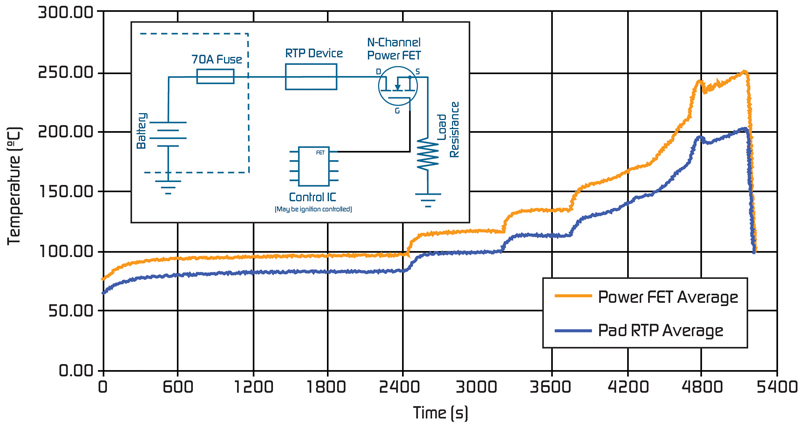
Reflowable thermal protection solution If a power component failure or a board defect generates unsafe overtemperature conditions the RTP device, which opens at 200°C (a value above normal operating temperatures but below lead (Pb)-free solder reflow temperatures), will interrupt the current and help prevent a thermal runaway condition that may lead to critical damage. As shown in Figure 2, when the RTP device is placed in series on the power line in close proximity to the FET, it tracks the FET temperature and opens the circuit before a slow thermal runaway condition can generate an undesirable thermal condition on the board.
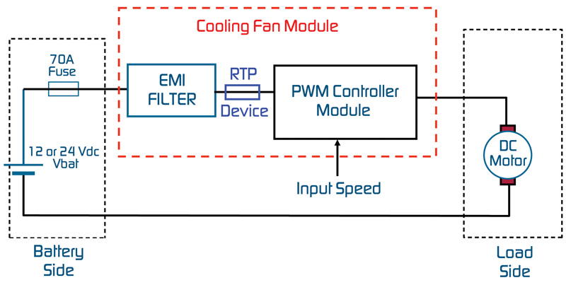
Protecting cooling fan modules from damage caused by thermal runaway Cooling fan modules (CFMs) are an essential element of the vehicle's HVAC and engine cooling systems, helping to cool the engine and prevent potential overheating under specific conditions, such as hot weather and steep hill driving. Figure 3 shows placement of the RTP device in a CFM application. CFM modules are typically placed under the hood and they experience more extreme temperature variations than those found in the passenger compartment. This thermal stress can accelerate fatigue of the powerFET and lead to early failure. Under-the-hood components may also be exposed to "fluid attacks" leading to corrosion and localized hot spots on the PCB.
Typically, CFMs do not include a micro-controller which, under certain conditions, could be used for onboard diagnostics and automatic initiation of the turn-off signal to the powerFET. As a result, a software approach to preventing powerFET failure is not available, and secondary protection is needed so that thermal runaway does not cause a dangerous thermal event. How it works The RTP device's 200°C open temperature helps prevent false activations and improves system reliability since it is a value above the normal operating window of most normally functioning electronics, but below the melting point of typical Pb-free solders. As a result, the device will not open if surrounding components are operating in their target temperature range, but it will open before a component de-solders and creates the potential risk of additional short circuits. To allow it to open at 200°C in the field, the RTP device utilizes a one-time electronic arming procedure to become thermally sensitive. Before arming, it can withstand three Pb-free solder reflow steps without opening. Timing of electronic arming is user-determined, and can be implemented to occur automatically at system power up or during system testing. Summary The RTP device helps protect against thermal-runaway damage caused by failed FETs, capacitors, ICs, resistors and other power components that can crack or corrode. The device's thermal sensitivity is beneficial since, in some cases, failed power components may not generate a dead short circuit overcurrent condition, but instead may create a resistive short that cannot be opened by a traditional fuse. This type of event may actually reduce load current, but can still result in thermal runaway conditions. The RTP device helps prevent damage caused by both dead short circuit and resistive short circuit conditions. www.circuitprotection.com