Author:
James Aliberti, Product Marketing Engineer, Power Supply Controls, Texas Instruments
Date
08/01/2010
 PDF
PDF
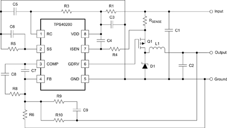
In many high-power lighting applications such as street lights, high-bay stadium lighting and others, the trend is moving towards solid state lighting that uses LEDs as the lighting source. The reason for this adoption is the clear value proposition of higher energy efficiency and less frequent maintenance, both factors justifying the transformation. In many high-power lighting applications such as street lights, high-bay stadium lighting and others, the trend is moving towards solid state lighting that uses LEDs as the lighting source. The reason for this adoption is the clear value proposition of higher energy efficiency and less frequent maintenance, both factors justifying the transformation. In these types of high-power lighting applications, a number of different approaches are being considered to drive theses lamps. In this article, we will look at a new topology boasting higher efficiency and lower system cost for driving multiple LED strings. To adequately measure the merits of this topology, we must first look at the various methods being considered, or that have worked well for lower power LED applications. One simple method is to use a power supply that converts mains voltage to a DC output voltage such as 12 or 24 volts. Then run parallel LED strings from it and using resistors in each string to regulate current. This is a low-cost approach. However, with today's high-brightness LEDs that can draw currents in excess of 350mA, this approach is very dissipative. It has low efficiency and produces poor current regulation that can cause noticeably different light output from string to string. To improve on this approach linear regulators replace the resistors, improving the uniformity of the light output of all the strings. But this is the only benefit as there is no noticeable improvement in efficiency or power dissipation. Reducing power dissipation is important to maximize LED life. In these two approaches, using either resistors or linear regulators act as localized heat sources, significantly reducing LED life. Another method that is also fairly simple is to make a long single series string, using a single power supply that produces a high-voltage DC constant current source. The high-voltage operation in this approach puts it above safety extra-low-voltage (SELV) levels of 60VDC or 42V RMS. It ties the lighting fixture or enclosure to the safety agency approval process and significantly reduces flexibility to apply the same electrical design to other applications. Another consideration with the single string approach is reliability. If just one LED opens, you loose the light output of the entire fixture. There are measures such as adding many crowbars or devices to clamp each open, but this adds cost and complexity to the light fixture. The most common method in high-power LED lighting applications is to use multiple string architecture with switching regulators for current regulation. Here a single main power supply converts the AC mains to a single DC bus voltage, usually within the SELV levels. This bus then supplies the parallel LED strings where each string has either a buck (most common) or boost converter. For simplicity sake, we will confine our analysis to the buck, as the boost from a cost and component count is very similar. For example, Figure 1 shows the low-cost simple buck regulator circuit. It consists of a PWM controller, inductor, MOSFET, diode and a handful of resistors and capacitors. If higher efficiency is required, you can replace the diode with a MOSFET and use a PWM controller that enables synchronous buck operation.
Figure 2 shows the various subsystem blocks for a high-power, multiple string lighting application with buck regulators for current regulation.
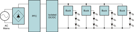
The AC mains input is rectified and fed to a power factor correction (PFC) boost circuit where the PFC produces a high voltage of 400V, which provides the input to a down stream isolated DC/DC converter. The DC/DC converter output is then used to produce a low-voltage bus, typically 12V or 24V range, providing power to the buck regulated LED strings. This approach has fairly high efficiency and is a good choice for minimal LED strings. However, for the higher power applications with four or more strings, the component count and cost can really add up. For electronic component manufacturers and the supply chain, this may be an appealing sell. However, for lighting manufacturers and their customers, the high cost can be detrimental to wide adoption. What is needed for solid state lighting's long term viability are low-cost drive circuits that can enable the market to take root and grow unimpeded. Figure 3 shows a series input, multiple parallel LED (SIMPLE) drive. It is a cost-effective approach for driving multiple LED strings. Excluding the PFC, it is a two-stage approach, comprising an inverted constant current buck regulator and a downstream DC/DC transformer circuit. It is highly efficient, has superior string current regulation and most importantly, a lower cost approach. It also can have inherent redundancy with a single passive acting silicon-controlled rectifier (SCR) crowbar added for each string. If an LED or string opens, it will not take down the remaining strings. Before we go into the operation, let's look at some of the things that immediately stand out when using the SIMPLE drive multi-transformer approach. First, notice that this is an electrically isolated design where secondary side output voltages can be designed to stay within SELV levels. When the output voltage stays within SELV levels, it eliminates the requirement to have the lighting fixture combined with the power supply, and interconnects to have safety agency approvals. Having the output within these levels adds inherent flexibility, allowing many varieties of fixtures addressing many other lighting applications. The power supply still requires safety approvals, just like all the off-line solutions discussed in this paper, but not the light fixture. Additionally, the isolated design can be significantly better from a thermal management perspective as there are no restrictions for LED proximity or contact to metal enclosures. Another feature that stands out is that it does not require feedback from the output side. This eliminates an opto or some other safety rated isolated feedback device. Finally, look at the simplicity of the secondary side. It has only a few passive components, and no bias supply, active components or control of any kind. When it comes to operation, the SIMPLE drive has superior string current matching of better than one percent. It has resonant operation for high efficiency and becomes more cost effective as the number of strings increases.
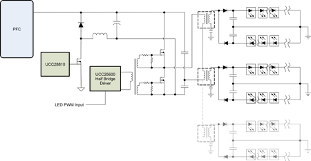
The output of the PFC circuit is the input of the inverted buck circuit. The inverted buck is configured to produce a constant current output. It is this current where the systems closed loop is around. The current output it produces is fed downstream to the DC/DC transformer circuit, which consists of a half-bridge controller, two MOSFETs, capacitors C1 and C2, and the transformers. This current is then circulated through the half-bridge MOSFET switches to the primary sides of the series transformers. Capacitors C1 and C2 serve a number of functions. They are used to set up a voltage divider for the half-bridge, are elements of the resonant circuit, and are DC-blocking capacitors, which help to prevent transformer saturation. The resonant operation allows the MOSFET switches to switch with zero voltage switching (ZVS). This reduces switching losses and forces the output diodes to zero current switch (ZCS), both adding to maximize efficiency. The DC current, now transformed to AC current, resonates back and forth through the primary side of all the series transformers. The number of transformer primaries that can be put in series is quite flexible as the winding ratios can be selected to support many transformers or LED strings. What needs to be considered for calculating turns ratios is the number of strings, as this dictates the number of transformers and the forward voltage of each string.
To achieve the highest possible efficiency in power conversion, the goal is to process the least amount of power as possible. To do this, we need to work as close to the input voltage as possible. Since most high-power lighting applications favor the use of active PFC, for simplification purposes we will just consider it as a functional block and assign some typical values to its output Since most active PFC circuits operate as a voltage boost, a PFC output voltage must be set higher than the peak of the highest AC line voltage. With a universal input range of 85 - 265VAC, this comes to about 375V. Adding some headroom for margin and tolerances, 400V has become a typical set point. To make sure that downstream buck has plenty of headroom from the output variations of the PFC, add a little more margin for ripple of about 40V. This makes our minimum input operating point for the inverted buck at about 360V. To assure that the buck output has some compliance voltage for it to work properly, give it some headroom as well and limit its output range to 280V. Now that we know our boundaries, let's look at a design example on how to calculate the value of the constant current from the buck and the transformers' turns ratio. In this example we use two transformers to drive four LED strings with 1A current. Each string has ten high-power LEDs. Assumptions: LED forward voltage Vf = 3.5V with a string voltage = 35V Since we set the output operating point of the DC buck at 280V, it now acts as the input to the DC/DC transformer circuit. This means that the voltage applied to the series primaries will be half that voltage from the capacitor voltage divider made up of C1 and C2, giving us 140V across the series primary arrangement. Calculating the turns ratio now becomes fairly easy as Equation 1 indicates: Primary Voltage (VP) of each Transformer = Bridge Voltage / Num Transformers = 140V/2 = 70V
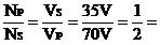
A turns ratio of 2:1 (Equation 1)
NP = Number of turns on the primary NS = Number of turns on the secondary VS = Secondary side or LED string voltage VP = Voltage across each primary winding To calculate the inverted bucks' current output set point, where each transformer drives two LED strings, it first must be recognized that only one string in each transformer is conducting in alternate half cycles. This means that the current that must be delivered to the conducting string to sustain LED conduction during the dormant period must be twice the LED current. In this case where 1A is the desired LED current, the current delivered to the LED and filter capacitor each half cycle is 2A. To calculate the buck regulator, set current point (ISet) is in Equation 2:
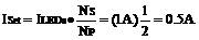
(Equation 2)
As can be seen, it is a very simple exercise to determine the transformer requirements, and makes the SIMPLE drive a very flexible solution to address a number of different lighting applications. If you intend to make SIMPLE drive as part of a modular approach strategy to your many LED lighting applications; you need to consider the upstream power stages such as power handling components in the half-bridge, inverted buck, and PFC as they must be sized to handle the highest power level you expect the drive to address. For more information about the SIMPLE drive multi-transformer, including reference designs, see the product folder for UCC28810: www.ti.com/ucc28810-ca, or evaluation module: www.ti.com/ucc28810evm003-ca. www.ti.com