Author:
Milan Marjanovic, Power Design Engineer, Texas Instruments
Date
01/07/2013
 PDF
PDF
Click image to enlarge
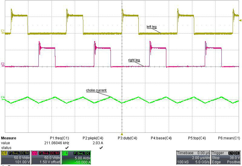
Figure 1: No load conditions: CH1-transformer secondary side, left leg; CH2-transformer secondary side, right leg; CH4 output choke current
High-speed bi-directional power supplies benefit from synchronous rectification, which plays a key role in backward power flow and greatly improved load-current transient response. This behavior, however, depends on never entering discontinuous conduction mode. This means if huge load-current steps of 0% to 100% are expected, then the converter has to stay permanently in continuous-conduction mode. Huge load-current steps produce negative current flow for a much longer period of time than only one switching cycle. A careful selection of regulation techniques in isolated power supplies with bi-directional power flow is, therefore, necessary. Voltage or peak-current mode? Many modern PWM controllers, such as the UCC28950 from Texas Instruments, provide a burst mode implemented to keep the efficiency high at light loads. Activating burst mode leads to a very low primary current and narrow duty-cycle operation on the output at light or no load. This means that the signal on the current sense pin is also very small. Furthermore, this condition inflicts a hundred-fold switching noise on the current signal in the millivolt range. This can cause controller instability, because the controller tries to regulate a peak current signal that is not clean enough. Because the peak-current mode needs voltage-slope compensation anyway, the only solution is to add even more slope compensation to keep the controller stable in this light-load condition. Then, however, it is moving away from a real peak-current-mode to voltage-mode regulation. Applying a large load-current step produces a large voltage drop at first on the output until the controller comes up from burst mode and the loop starts to react. Disabling the burst mode is the right approach for this high-speed bi-directional application. In this case, the synchronous rectification works continuously and the duty cycle remains almost constant over the entire load range. Here again, however, at light- or no-load conditions the current-sense signal is still small and, additionally, has a negative component. The explanation is simple: the current in the output inductor has two components: an average DC current and an alternating ripple current. At no load, the average current is zero but, due to the synchronous rectification, the current in the inductor remains continuous, therefore the alternating component is ever present (figure 1).
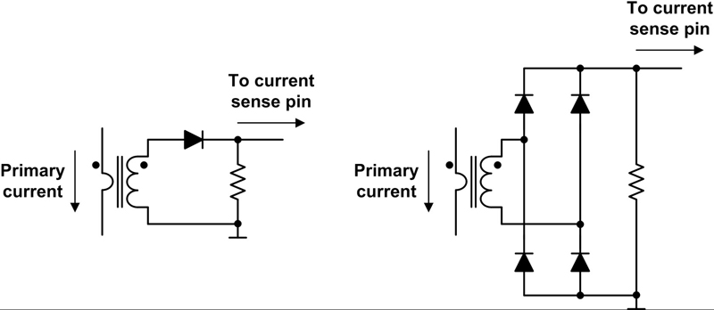
This behaviour forces the current sense signal on the primary side to zero for each period of cycle when the current is negative (flows back from the secondary side to the primary side). The higher the ripple current, the more negative this voltage. Because a diode blocks the negative voltage in the unipolar current sense, the voltage on the current sense pin of the controller is approaching zero (Figure 2). Now, if the dead time between each switching cycle is not large enough for demagnetization of the transformer, it will go into saturation.
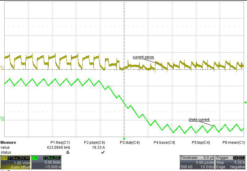
Together this scenario is problematic and can confuse the controller, especially during large load-current steps. In this case, even high slope compensation doesn't help to keep the converter stable. Figure 3 shows a high load-transient down slope of 1 A/μs. The average current crosses the zero level, becoming negative, and remains there until the overloaded energy returns to zero. In the meantime, the signal on the current sense pin has negative slope. A controller working in peak-current mode cannot regulate under these conditions. So, sensing unipolar current with a current-sense transformer is only suitable for converters where the current flows only in one direction, that is not in bi-directional mode. Unipolar current sensing requires a high-voltage diode with low parasitic capacitance and leakage current. Such sensing also requires a clamping circuit to protect against the energy overshoot coming from the leakage inductance caused by the current-sense transformer. The experience gained during development showed that achieving a good transient response at load steps from 0% to 100% requires bi-directional working capabilities. Two requirements have to be fulfilled: • The PWM controller has to work in voltage mode. • Protection in the form of cycle-by-cycle over-current limitation is necessary. Therefore, the current-sense transformer has to connect in series with the full-bridge transformer's primary winding. This ensures demagnetization, even when a negative current is measured (current flow from the secondary side to the primary side).
To protect the full-bridge transformer against saturation in voltage mode, the easiest way is to place a capacitor in series with the transformer. This blocks any DC component caused by any waveform asymmetry. The type and value of this capacitor is defined by the accepted ripple voltage and primary peak current. Usually in this case, 2% of the input voltage is allowed for the ripple voltage and a X7R capacitor is well suited for this task.
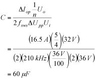
At the switching frequency of 210 kHz and minimum input voltage of 36 V, the capacitor needs to be 60 ?F minimum. Considering the tolerances and allowable ripple current, we chose two 47-uF capacitors with the X7R dielectric. By combining the capacitors in parallel, PCB routing is easier and the parallel connection reduces the circuit's overall RESR. As shown, unidirectional current sensing works well only if the current remains in the same direction of flow. On the other hand, bi-directional current sensing works only with alternating current. As the current sense transformer connects in series with the primary winding of the full-bridge transformer and the system is working in voltage mode, this demand is fulfilled. Furthermore, the transformer is demagnetized inherently as only AC current flows due to the capacitor in series with the full-bridge transformer. The rectification of the current signal is not an issue any longer: the circuit can use low-voltage Schottky diodes. In voltage mode with bipolar current sensing, the current-sense signal is only used for protection. If the signal hits the threshold, the controller goes into cycle-by-cycle peak-current limit. For this reason, slope compensation is needed again. Recommendations: • Use a topology with synchronous rectification for a high-performance and high-speed power supply to achieve a good load-transient behavior. • Disable any burst or power-safe mode and enable continuous conduction mode all the time. This reduces efficiency at low or no load conditions, but is the only way to react fast to large load-current changes. • Avoid any components with low-pass behaviour like an optocoupler in the voltage feedback loop. The highest bandwidth is achieved, if the PWM controller is placed on the secondary side. • Use voltage-mode control and bi-directional current sensing to avoid instabilities when current flows backwards (from the secondary side to the primary side). Texas Instruments