Author:
Joshua Israelsohn, Editor-in-Chief, Power Systems Design
Date
08/02/2012
 PDF
PDF

[Editor's note: Part one of this Wind Power 2012 event review is available here.]
For those of us who approach the subject from an electrical-engineering background, it's all too easy to get caught up in the electric works and forget that success in wind power depends on multiple disciplines. Just as in microelectronics, where victory eludes those who do not respect the demands of the mechanical and thermal aspects of design, you won't generate a dollar or a kW without addressing the myriad non-electrical challenges to converting wind into electrical energy. Energetx Composites is one of many suppliers that take on some of those non-electrical challenges. The company makes advanced structural composites for the energy, transportation, and defense markets. Within the energy sector, Exergetx's focus is on utility- and community-scale wind blades, nacelles1, and spinners2. On the large end of the scale, the company is supplying blades as large as 45.3 m for 2-MW turbines operating in a Class-2 environment (table 1). Blade fabrication is not just a matter of getting the shape right. These are highly engineered structures and the fabricator must calculate in advance a great deal of information about how the blade will perform under the stress of real-world operating conditions.
Prior to deployment, blades designs must pass qualification tests for a given class. These tests, performed at an independent laboratory, require instrumenting the blade with strain gauges, applying loads, and comparing the resulting strain measurements to the design-engineering values. Depending on the nature of the test, loads may be static or dynamic. The test takes the structure to its proof load to ensure it meets engineering expectations at its rated limits. Fatigue testing assesses the blade's performance over repeated stress cycles to gauge the blade's mechanical reliability. Finally, the test facility stresses the blade to its failure point, measuring its deformation along the way. The test compares the failure-inducing stress magnitude to the manufacturer's design prediction and looks to confirm that the blade fails in the mode that design data predicts. According to Energetx Vice President of Business Development, Kelly Slikkers, the company engages the WTTC (Wind Technology Testing Center) in Boston, Massachusetts for its qualification testing (figure 1). The MCEC (Massachusetts Clean Energy Center) built the WTTC—one of the world's largest blade testing facilities—in partnership with the US DOE (Department of Energy) NREL's (National Renewable Energy Laboratory's) NWTC (National Wind Technology Center). And that, dear reader, is why engineers should never challenge bureaucrats to acronym contests. The WTTC can provide a maximum static bending moment of 84 MNm. The facility accommodates blades of up to 90-m length, depending on test specifications, and can displace the test-subject blade's tip as far as 32 m in the horizontal axis and 21 m in the vertical. The facility tests to popular standards including those of the IEC (International Electrotechnical Commission), GL (Germanischer Lloyd), and DNV (Det Norske Veritas). The WTTC can provide bending-moment tracking, strain-distribution measurement, and stiffness calibration. For fatigue testing the WTTC uses the NREL/MTS UREX excitation system in which hydraulic cylinders actuate linear moving masses on the blade at one or more locations. The system simulates more than 20 years of cyclic field loads in only months. And you thought life testing electronic devices took a long time.
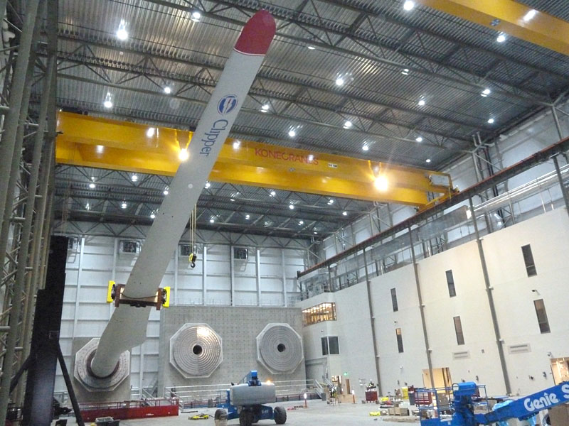
Though equipped with a pair of 50-ton overhead bridge cranes, positioning a 90 m blade, or even one of Energetx Componsites' 45.3 m blades, requires that facility operators can move it to within an overhead crane's reach. Transporting blades from their manufacturers to the test facility is not the sort of job for which one calls Federal Express. Logistically, the testing facility must have direct access to transportation on a scale commensurate with the components under test. This doesn't hold only for blades but for other large components as well. For example, Clemson University took advantage of rail and ship-handling infrastructure adjacent to a decommissioned Navy warehouse in North Charleston, South Carolina—now the site of their new WTDTF (wind-turbine drivetrain testing facility). The site includes deepwater port access that can accommodate a 42-foot draft and provides 500-ton lift capacity at the dock. The testing facility—one of the largest such installations in the world—includes a dedicated rail spur that runs from dock to door. Inside the door, however, is where things get far more interesting: Acording to WTDTF Project Manager James Tuten, the test facility includes 15 MW and 7.5 MW dynamometer test stands with off-axis force applicators. The applicators replicate forces and moments along the three orthogonal axes, simulating blade forces the system under test will experience in the field. The 15 MW stand can apply dynamic loads; the 7.5 MW stand is currently limited to static-load tests but Clemson could upgrade it to dynamic loading at a future date if they see sufficient client demand. The facility can test direct-drive and geared?drive turbines at 50 or 60 Hz and recirculates power during testing to reduce costs (table 2). A 750-channel high-speed data-acquisition system, designed by the SRNL (Savannah River National Laboratory), integrates electrical grid monitoring, vibration monitoring, facility instruments and sensors, and turbine vendor's sensors.
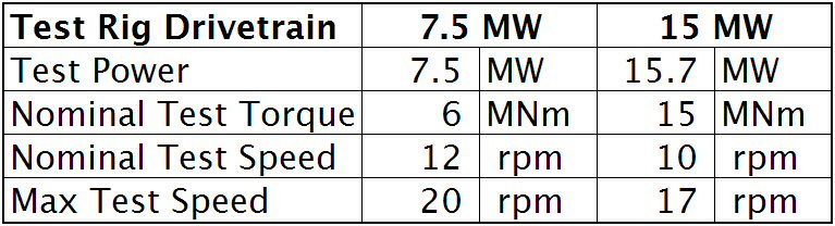
Source: WTDTF Spec Sheet
In both cases—the WTTC in Boston and the WTDTF in North Charleston—have sufficient proximity to shipping facilities that they can serve distant markets, which is fortuitous considering the significant fraction of wind-power projects that lay far beyond these shores. Links Energetx Composites NREL (National Renewable Energy Laboratory) WTTC (Wind Technology Testing Center) MCEC (Massachusetts Clean Energy Center) Clemson University SRNL (Savannah River National Laboratory) Footnotes 1. The nacelle is the protective housing that contains wind turbine components including the generator, gearbox, low- and high-speed shafts, controller, and brake assembly. 2. The spinner is the conic structure that attaches to the front of the blade-assembly hub. Though this may sound as exciting as a hubcap on your car, several research projects are comparing spinner-mounted anemometers to sonic 3D wind sensors with encouraging results. Thus far, the automotive industry has yet to announce plans to generate critical operational data from the caps on their hubs. 3. Vertical extrapolation of wind speed based on the 1/7 power law. 4. Each wind power class spans two power densities. For example, Wind Power Class 3 represents the Wind Power Density range between 150 W/m2 and 200 W/m2. The offset cells in the first column illustrate this concept. 5. Mean wind speed is based on Rayleigh speed distribution of equivalent mean wind power density. Wind speed is for standard sea-level conditions. To maintain the same power density, speed increases 3%/1000 m elevation.