Technical Features

September 2013
DC/DC Flyback Converter

Click image to enlarge

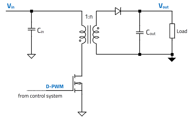
Figure 1: Power stage of the flyback converter (simplified)

Isolated flyback converters often use optocouplers in the feedback loop to regulate the output voltage. As part of the compensation circuit, its parameters such as CTR influence the control loop and must be taken into account in the flyback converter design. The flyback converter is an isolated switching power
Date:
04/01/2024
What is the Smart Grid, really?

Click image to enlarge

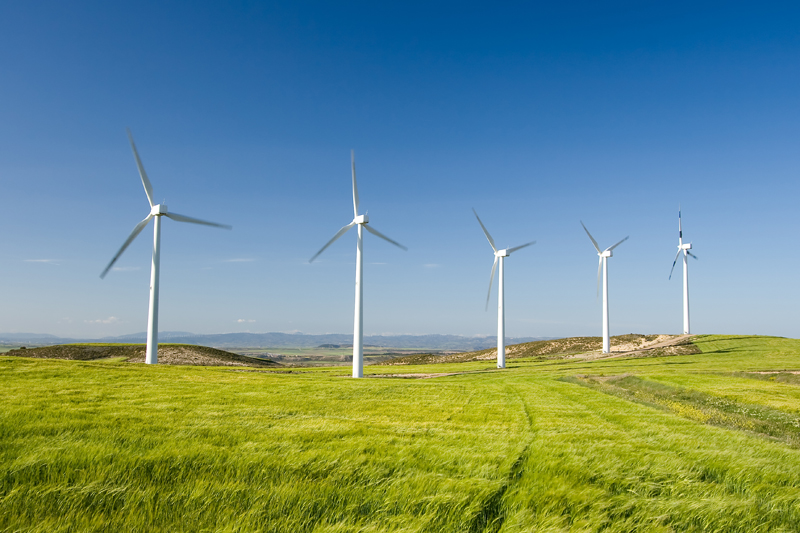
Figure 1: Escalating installations of renewable energy sources are likely to be distributed far and wide

The Smart Grid - a changing landscape of supply, demand and storage Definitions of the "Smart Grid" range from highly technical descriptions to purely commercial interpretations, but whichever one
. . . Learn More
Date:
09/26/2013

Understanding power factor and the need for power factor correction

Click image to enlarge

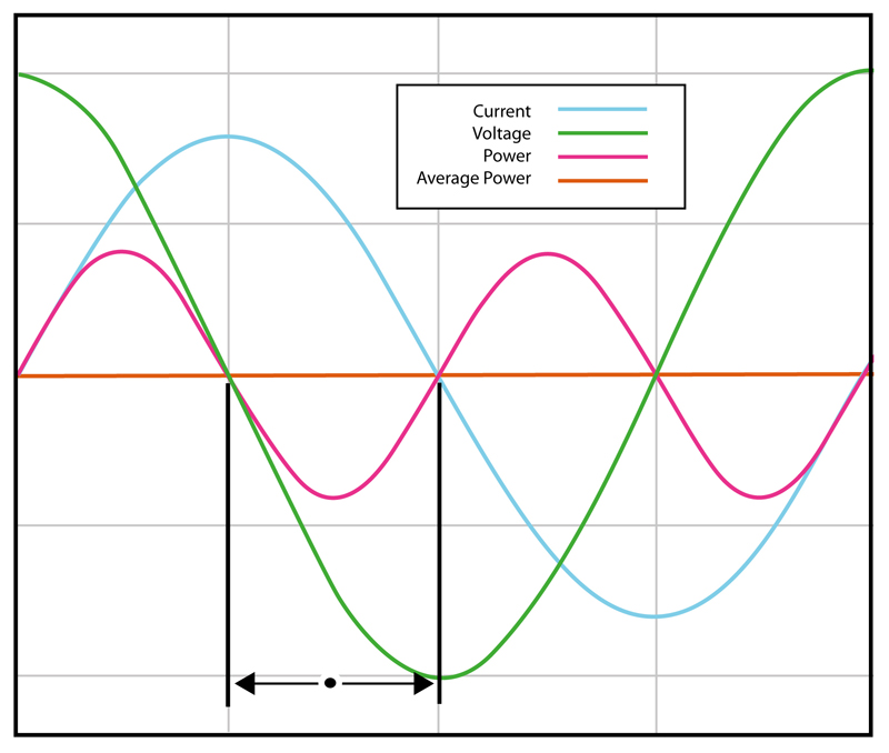
Figure 1: An ideal waveform with a power factor of 0

Until the era of switching power supplies, Power Factor - and power factor correction - wasn't a big concern for all but a handful of electrical engineers working with large electric motors, and other,
. . . Learn More
Date:
09/24/2013
Selecting the Right MOSFET for Power Factor Correction Applications

Click image to enlarge

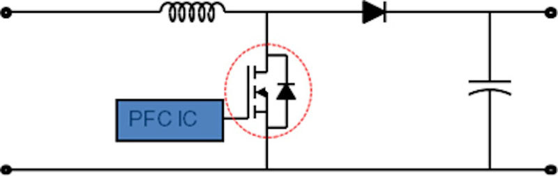
Figure 1: PFC schematic

Power factor is the ratio of the real power (P = Watts) to the apparent power (VA = Volt Ampere); the goal is to achieve a power factor as close to 1 as possible. A load with a lower power factor
. . . Learn More
Date:
09/19/2013
Online Design for FPGA Power

Click image to enlarge

Figure 1: High-level schematic showing the power tree for an Altera Stratix III FPGA.

The Internet has become a key resource used by engineers to obtain information. In spite of the wealth of data, the assimilation and practical application of information remains a challenge. Cloud
. . . Learn More
Date:
09/05/2013
Archives


-->