The device combines very low on-state voltage losses with fast turn-on behavior
The latest 4.5kV IGBT/diode chip set from Infineon has been developed and optimized for HVDC applications. It features very low on state voltage losses combined with fast turn on behavior for high current, high voltage and high robust short circuits behavior. High robustness will be demonstrated using HDR technologies for IGBT and diode. The 4.5kV class supplements the already existing high voltage classes of 3.3 kV and 6.5 kV. The chip set will be available in two different housings.
The first is a highly insulated 6.5kV module housing, offering 10.2kV isolation capability and corresponding creepage distance and clearance distance as requested by the harsh environment of traction applications with DC link voltages in the range of 2500-3000V. The second chip set is designed for the IHV-B housing, the successor of the well-known and worldwide applied IHV-A module. This module addresses industrial applications like medium voltage drives and the wide field of High Voltage Direct Current (HVDC) as well as flexible-AC-transmission-system (FACTS) applications. The module is shown in Figure 1.

Click iamge to enlarge
Fig. 1: The 4.5kV FZ1200R45HL3 module
These IGBT-based voltage source converters (VSC)will play an important rolefor future HVDC systems – in contrast to the well-known thyristor-based grid-commutated high-voltage DC transmission. IGBT-based solutions are independent active- and reactive-current control due to the turn-on and turn-off capability of the IGBT. Additionally, they show a superior performance in case of AC-grid faults.
For high voltage applications a large number of semiconductors used to be connected in series and simultaneous switching with high accuracy had to be ensured. In order to facilitate this demanding design a multi-level VSC – Modular Multilevel Converter MMC – for high voltage applications like HVDC and FACTS was proposed. The switching frequency of individual IGBT modules can be reduced in HVDC applications. Therefore low on-state losses are of special interest in order to reduce the overall power consumption.
IGBT and diode structure
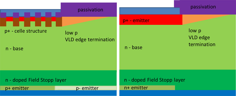
The IGBT trench technology provides low on-state losses due to the carrier accumulation effect between the cells together with an optimized cell pitch, and an optimized channel length as well as channel width designed for high blocking voltages. As a result, the trench technology offers a feasible way to influence the charge carrier concentration below the cell within a wide range compared to the standard planar technology. Figure 2 depicts the schematic cross sections of the 4.5kV IGBT/diode. For the edge termination for both devices a VLD structure (varied lateral doping) has been applied. In combination with the vertical HDR structure this leads to an extreme high turn-off robustness of the IGBT and commutation robustness of the diode, respectively, due to the reduction of dynamic avalanche phenomena during the switching sequence.
Click image to enlarge
Fig. 2: Schematic cross section of the IGBT (left) and EC diode (right) with HDR and VLD edge termination
Electrical performance
Static characteristics
To realize low on-state voltages for the 4.5kV IGBT the well-known trench technology from the 6.5kV device platform has been adapted. This includes a suitable base material, an adapted field stop and an optimized cell design that results in the best-in-class on-state characteristic for 4.5kV devices. At 1200A, the nominal current of the FZ1200R45HL3 module, a typical VCE(sat)=2.35 V at 25°C, VCE(sat)=2.9 V at 125°C and VCE(sat)=3.0V at 150°C temperature are realized. The EC diode exhibits an almost neutral temperature coefficient at nominal current of 1200A and a typical forward voltage drop in the range of Vf≤2.5V in the temperature range of 25°C ≤ T ≤ 150°C.
Dynamic characteristics
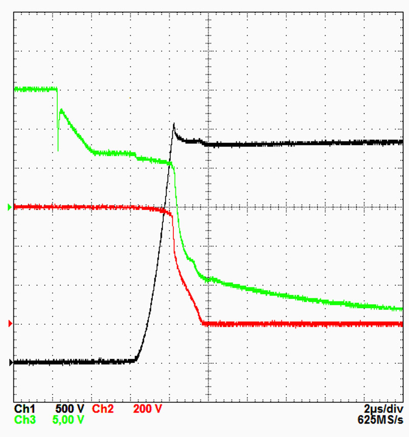
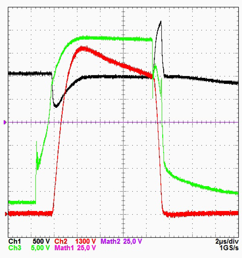
Switching waveforms at nominal conditions, i.e. VCE=2.8kV, IC=1200A and T=150°C are shown in Figure 3. Under these conditions a soft turn-off behavior for a commutation inductance of 150 nH can be seen. The VCE does not exceed 3.4kV. A soft turn-off is also ensured for harsher conditions, i.e. higher stray inductances, higher currents and operation temperatures down to -40°C. Typical turn-on and reverse recovery waveforms are depicted as well. They reveal a very smooth IF tail gradient.
Click image to enlarge
Fig. 3:a Typical waveforms at 2800V / 1200A, 150µH, 150°C
Click image to enlarge
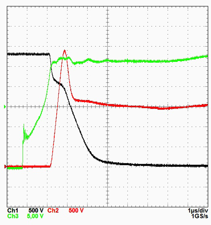
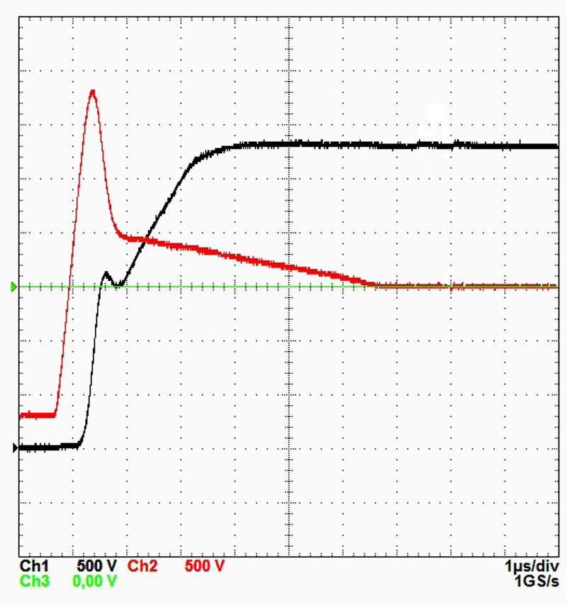
Fig. 3b: Typical waveforms at 2800V / 1200A, 150µH, 150°CSwitching at high voltage and high current
Clcik image to enlarge
Fig. 3c: Typical waveforms at 2800V / 1200A, 150µH, 150°C
turn-off: VCE=400V/div, IC=150A/div, Rgoff=5.1W, VGE=5V/div
turn-on: VCE=350V/div, IC=300 A/div, Rgon=1.2W, VGE=5V/div
reverse recovery: VCE=500V/div, IC=500A/div, Rgon=1.2W
For HVDC applications it is important that in case of a failure event the IGBT shows a rapid turn-on behavior at high voltage and high current in time. The device’s ruggedness under such conditions beyond the RBSOA limits has been evaluated.
Amongst others, the channel width is one possible IGBT parameter for adapting the turn-on behavior to a predictable failure event. In case of an increased channel width a rapid turn-on performance can be achieved. At the same time, however, the increased channel width is suffering from short circuit capability due to an increased short circuit current. Hence, a compromise between turn-on performance and short circuit capability has to be found. Alternatively, the vertical structure of the IGBT is enhanced to fulfill both of these requirements.
Short circuit capability
In order to prove the short circuit type 1 capability of the IGBT tough conditions such as VCE=3000V, VGE=17V and T=125°C have been applied. 9500A, nearly 8 times of the nominal current, have been switched off. The vertical IGBT structure has been optimized to prolong the lower limit of short-circuit time until device failure. In Figure 4 a short-circuit waveform is shown. The short-circuit event can be handled by the IGBT module FZ1200R45HL3 and a reliable turn-off is granted even after a short-circuit duration of 10µs.
Click image to enlarge
Figure 4a short-circuit waveform is shown.
Robustness of IGBT and diode
For HVDC applications as well as for traction applications a high over-current turn-off capability for IGBT and diode is improving the systems reliability.
By applying the HDR concept the impact of the termination system on the IGBT robustness can be neglected. Only the cell design constitutes a limiting factor. The trench structure allows for a further reduction of the source length of the IGBT. Due to the fact that the current density decreases inversely proportional to the source length, the latch-up immunity of the trench IGBT is effectively improved and excellent turn-off ruggedness is obtained.This is demonstrated by switching five times the nominal current without severe oscillation on current or voltage signals.
In addition to a low on-state voltage the new 4.5kV EC diode reveals low dynamic power losses in combination with a very high robustness. The diode recovery has been tested for a 200A nominal current module with Pmax≥4MW without destruction.
Surge Current capability
In an event of failure, e.g. short circuit in the power transmission line, fault conditions such as high surge currents can occur during diode operation. Therefore, the ability to withstand high surge currents is an important criterion for the usability of the module. Sufficient surge current capability can be realized by an optimized vertical design resulting in a low VF together with the HDR concept. For a module with IC=1200A a typical IFSM value of about 10kA can be reached which corresponds to a I2t of about 500 kA2s at 125°C temperature or 460 kA2s at 150°C.
Cosmic radiation robustness
The 4.5 kV IGBT and emitter controlled diode is designed for high robustness against cosmic radiation. The vertical device structure shows low electrical field strengths at typical DC-link voltages. The typical FIT rate, number of failures in 109h operation hours, for the FZ1200R45HL3 module at ~3kV DC-link voltage has been determined as 100 FIT. Besides the steady state situation during blocking the DC-link voltage the cosmic radiation robustness under switching operation has also been considered. Simulations confirmed that an additional dynamic FIT rate can be neglected for dV/dt up to 2kV/µs due to a limited electric field within the device.
Summary
The newly presented 4.5kV trench field stop IGBT and emitter controlled EC diode have been designed for industrial applications and, in the IHV-B package, especially for HVDC applications. The IGBT and diode performance features a very low on state voltages and fast turn on switching behavior of the IGBT especially for high voltage and high current beyond the standard conditions. Simultaneously, the FZ1200R45HL3 module shows a high short circuit performance. Furthermore, an extremely high IGBT and diode robustness during over current turn-off is demonstrated. The new devices are designed for an operation temperature of up to 150°C. These features were realized by adaption of the trench cell design as well as the vertical structure of the 6.5kV IGBT using the HDR technology.