Technical Features
Click image to enlarge

Click image to enlarge
Figure 1: A PIID acts as a permanent technical address that survives ownership transitions and software migrations, preventing the 'institutional amnesia' typical of multi-decade asset lifecycles

Click image to enlarge
Figure 1: Basic Buck Converter Circuit (SWA Is On)

Click image to enlarge
Figure 1: Data Center Power Distribution Architecture Evolution

Click image to enlarge
Figure 1: Unlike previous solutions, MotionMate can also be actively opened

Click image to enlarge
Figure 1: a demonstration of how electrohydrodynamic (EHD) airflow is achieved

Click image to enlarge
Click image to enlarge
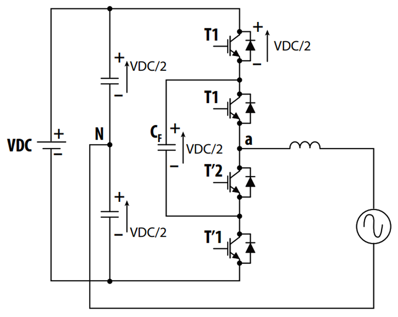
Figure 1: Simplified three-phase flying-capacitor inverter topology
Click image to enlarge
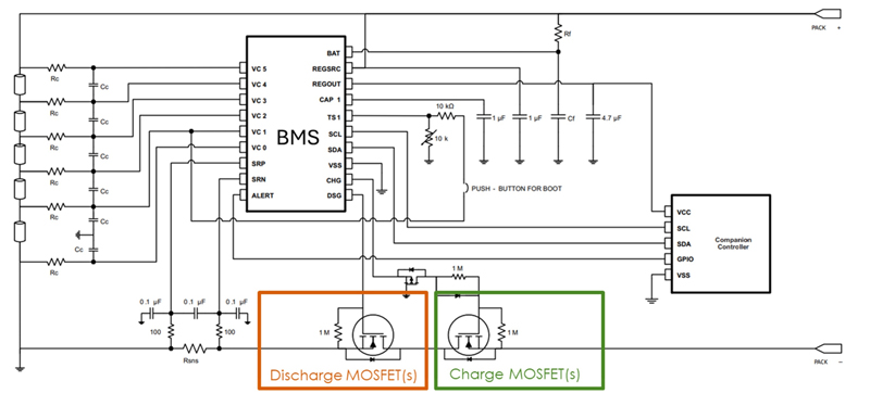
Figure 1: Simplified BMS topology showing charge and discharge MOSFETs
Click image to enlarge
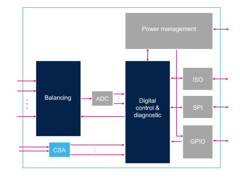
Figure 1: Simplified block diagram for the L99BM114 BMS
Click image to enlarge
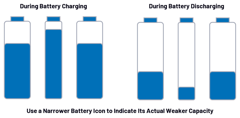
Figure 1: Impact of capacity-mismatched cells during battery pack charging and discharging

Innovation through Lean AI
Jun 1,2026
Molded Power Inductors
May 29,2026

