Technical Features

    November 2012
    Transformer Design Comparisons for Mitigating EMI in Gate Driver Circuits

    Click image to enlarge

    Figure 1: Gate driver circuit diagram with a Bourns transformer

    While gate driver-based converters deliver improved efficiency, speed and signal integrity, their high frequency switching features can produce elevated levels of conducted electromagnetic interference (EMI), posing challenges to electromagnetic compatibility (EMC) and overall system reliability. To solve this
    Date:
    03/29/2026
    New technology and acquisitions benefit wireless sensing

    Click image to enlarge

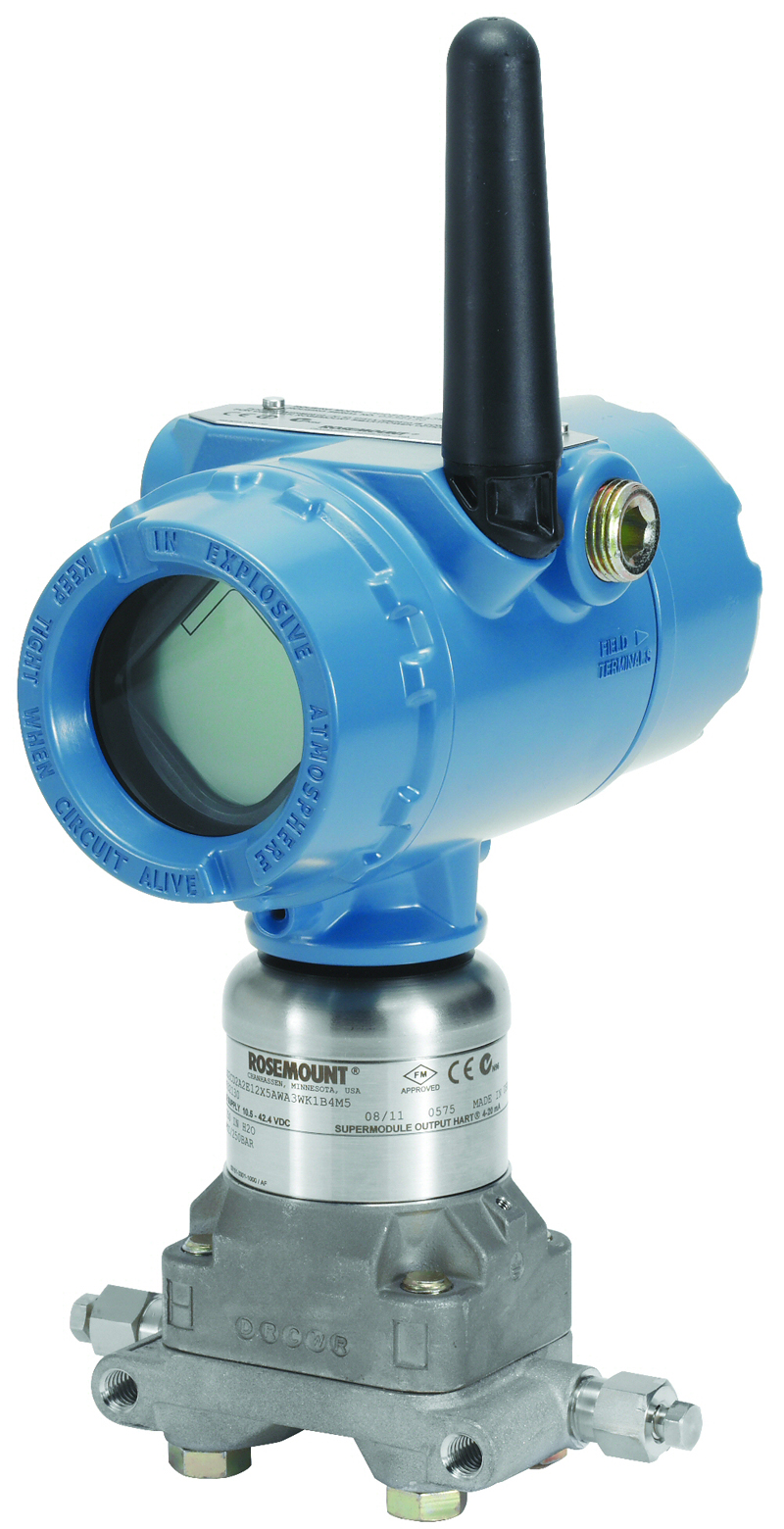
    Figure 1: Emerson Rosemount's 3051S series wireless instrumentation exemplifies the benefits WSN brings to industrial applications: It can reduce total installation costs by 45% and total deployment time by as much as 75%, eliminating design and installation time and cost associated with wiring, conduit, cable trays, and junction boxes.

    Wireless sensing is the most important new technology in process measurement to appear in decades. For this reason alone, it has attracted the sustained attention of ARC Advisory Group and other industry
    . . . Learn More
    Date:
    11/27/2012
    Making the switch to silicon carbide

    Click image to enlarge

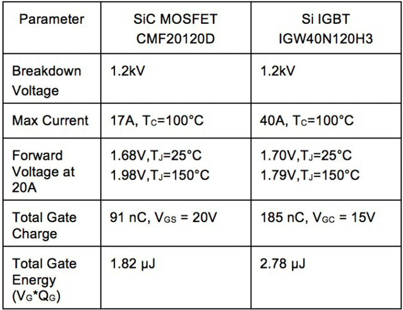
    Table 1: SiC MOSFET and Si IGBT comparative specifications

    To demonstrate the advantages of silicon-carbide MOSFETs versus silicon IGBTs (insulated-gate bipolar transistors) when used in high-power, high-frequency circuits, it is necessary to employ a test
    . . . Learn More
    Date:
    11/19/2012
    Medical applications demand mixed-signal ICs for high reliability

    Click image to enlarge

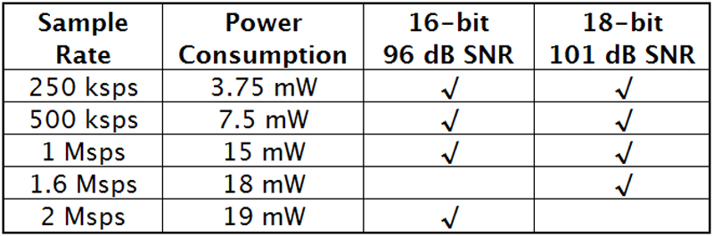
    Table 1: The LTC2376 through 2380 pin-compatible family of differential, no-latency SAR ADCs are available in 16- and 18-bit versions.

    Advances in medicine and medical treatment bring the promise of more-accurate diagnoses, new treatment methods, and more patient-friendly medical care. From high-resolution imaging systems to drug-delivery
    . . . Learn More
    Date:
    11/08/2012
    Measure VSWR to quantify transmission-line imperfections

    Click image to enlarge

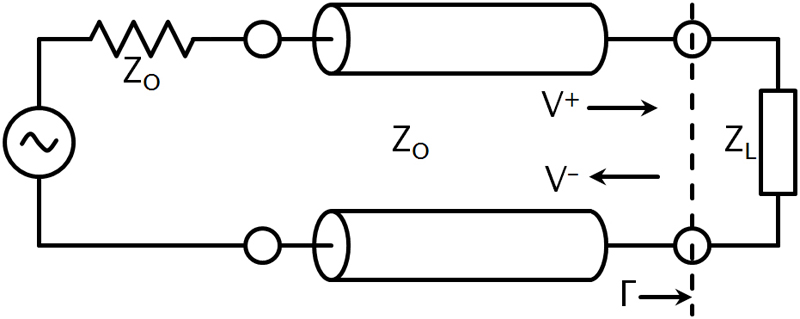
    Figure 1: Transmission line circuit illustrating the impedance mismatch boundary between the transmission line and the load. Reflections occur at the boundary designated by ?. The incident wave is V+ and the reflective wave is V-.

    Impedance mismatches in an RF transmission line causes power loss and reflected energy. The VSWR (voltage standing-wave ratio) is a way to measure transmission line imperfections. In an RF electrical
    . . . Learn More
    Date:
    11/07/2012
    Designing with digital power for optimum system performance

    Click image to enlarge

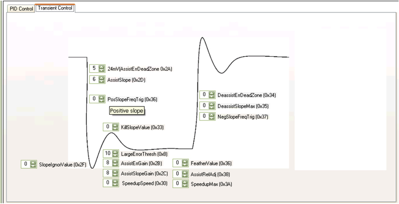
    Figure 1: Optimising transient response parameters via a digital-power GUI.

    Digital power has emerged to satisfy the need for power supplies capable of handling the complex and rapidly changing power demands of high-performance computing subsystems. These include equipment
    . . . Learn More
    Date:
    11/01/2012
    Archives

    Power Systems Design

    146 Charles Street
    Annapolis, Maryland 21401 USA

    Power Systems Design

    Published by Power Systems (PSD) serves all aspects of the Power Electronics market including but not limited to Power Conversion, Power Management, Intelligent and Embedded Motion, Automotive, Renewable Energy, Energy Efficiency and Lighting. PSD is published 10x per year in English with separate print editions for Europe and North America and is published 6x per year in China. PSD Apps are available for Android & iOS. Additionally qualified power engineering professionals may subscribe and receive PSD daily PowerSurge newsletters.