Technical Features
August 2018

Click image to enlarge
Figure 1: Gate driver circuit diagram with a Bourns transformer
While gate driver-based converters deliver improved efficiency, speed and signal integrity, their high frequency switching features can produce elevated levels of conducted electromagnetic interference (EMI), posing challenges to electromagnetic compatibility (EMC) and overall system reliability. To solve this
. . . Learn More
Date:
03/29/2026
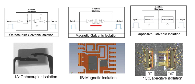
Figure 1: Various Galvanic Isolation Technologies
Capacitive isolation is a mature solution developed over the past decade to replace optocouplers in signal isolators, isolated gate drivers, isolated transceivers, and other applications. However, the potential to use capacitive isolation to replace optocouplers in offline adaptors is often neglected. This articles ex
. . . Learn More
Date:
08/31/2018
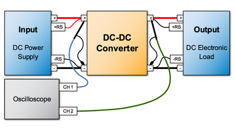
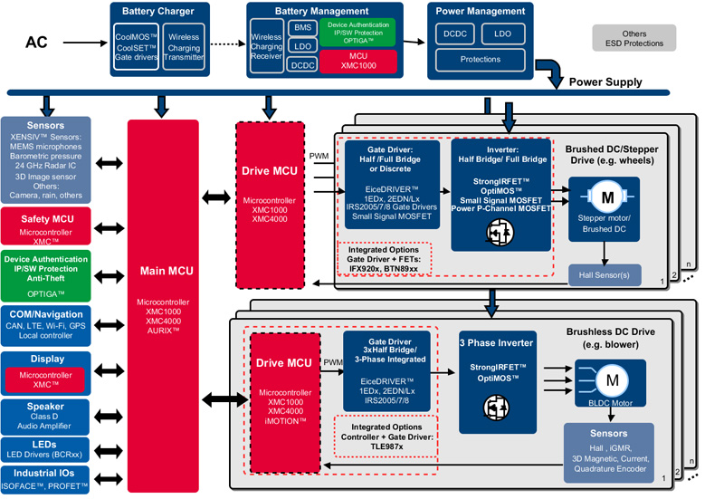
Figure 1. Block Diagram
An automotive DC-DC converter receives high-voltage battery output and converts it to a lower voltage to power on board devices such as the instrumentation panel, entertainment system, sensors, LED lighting, and any other on board devices requiring low voltage DC power. Manufacture’s strategies in DC-DC co
. . . Learn More
Date:
08/31/2018
People have been infatuated with controllable machines for a very long time. Today robots are in our immediate surroundings, leaning away from industry-based usage and shifting the focus toward becoming our everyday helpers. With the commercialization of robots, modern engineering designs stress how important it
. . . Learn More
Date:
08/31/2018
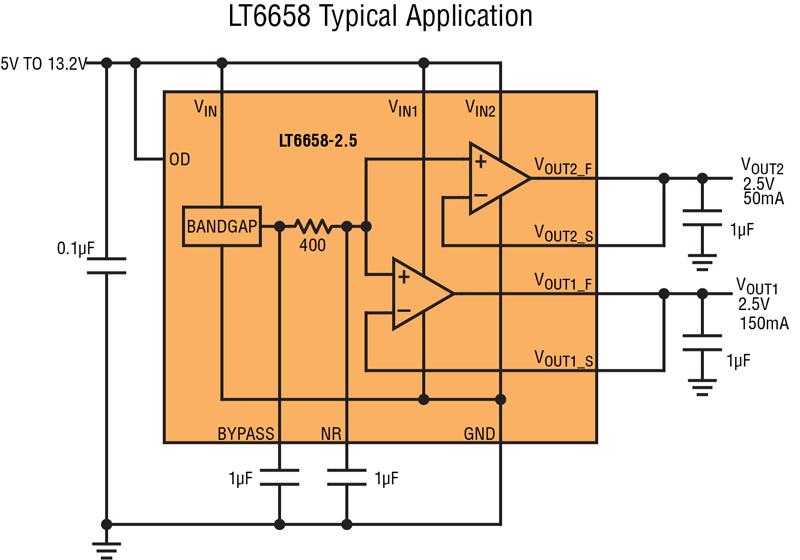
Figure 1. LT6658 Typical Application
Precision analog designers often rely on the quiet humble voltage reference to power their DAC and ADC converters. This is beyond the fundamental role of the reference, which is designed to solely provide a clean precise stable voltage to a converter’s reference input. With some caveats, this usually works, wh
. . . Learn More
Date:
08/30/2018
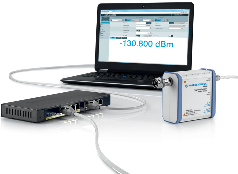
Figure 1: Hardly larger than a conventional sensor, but with unparalleled dynamic range: the R&S NRQ6 frequency selective power sensor.
It may sound obvious, but for precise power measurements with RF signals the instrument of choice is an RF power meter. Two power detection technologies have become established: thermal measurements and diode measurements. Thermal power sensors determine power based on the heat generated by an input signal in a
. . . Learn More
Date:
08/30/2018
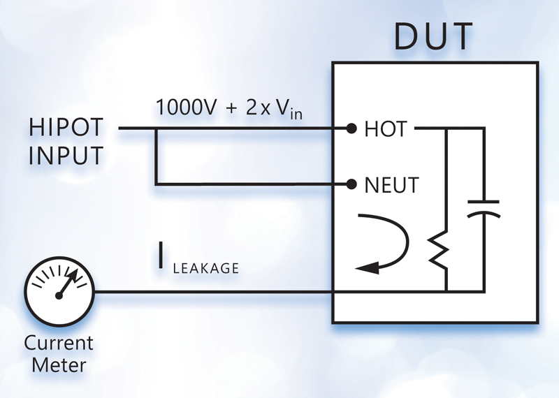
Figure 1. Hipot is applied to both conductors and leakage is measured in return circuit through the ground connection
Hipot testers offer a range of capabilities starting with dielectric withstand and insulation resistance testing but also, in many instances, providing accurate low-resistance measurements and low-resistance/high-current outputs to test ground resistance and ground bond integrity. Selecting the right one for
. . . Learn More
Date:
08/30/2018
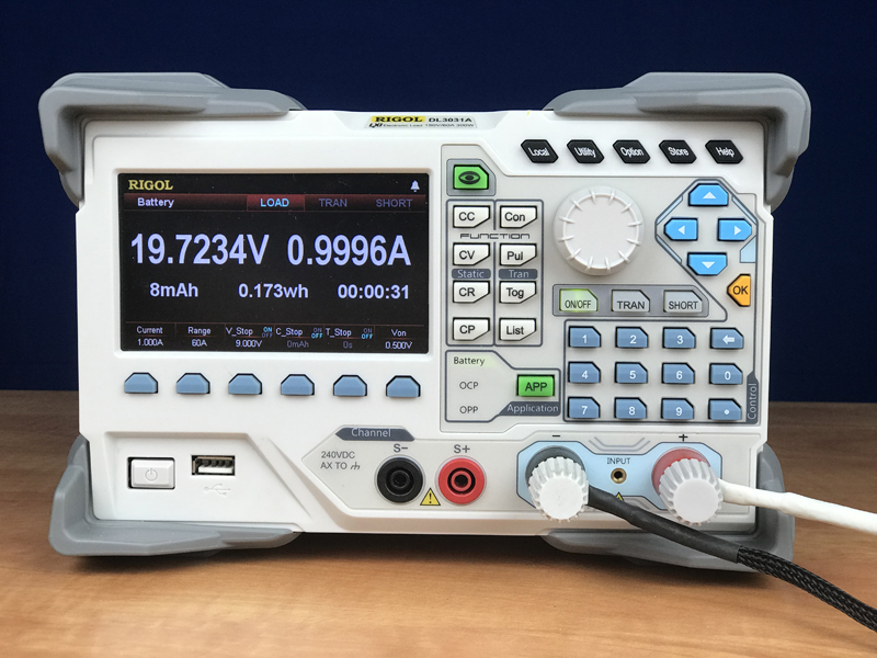
Figure 1 – Battery Application mode on RIGOL’s DL3000 Series Electronic Load
As the electronics industry continues to grow, so does the need for better batteries, and battery technology that reduces their size, improves their reliability, and increases their capacity. Engineers require an instrument that is capable of testing batteries to ensure they can meet the requirements of th
. . . Learn More
Date:
08/30/2018
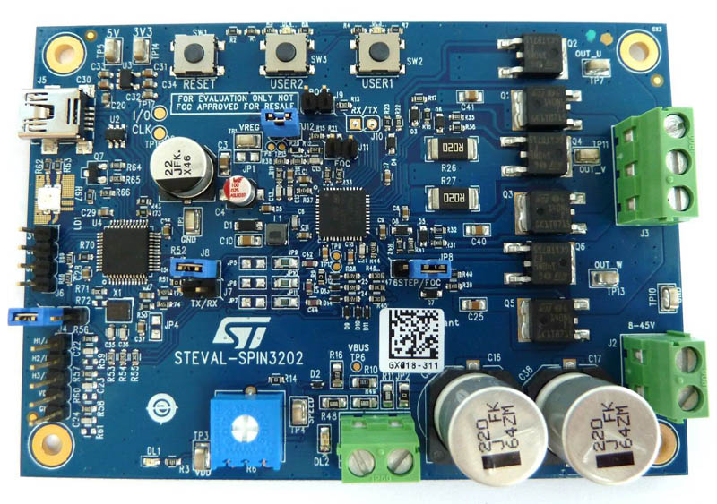
Figure 1 - PC Board
As car manufacturers strive to find ways to increase energy efficiency, and therefore reduce CO2 emissions, the adoption of low-powered, low-weight electric motors for auxiliary units - which work separately from the main drive motor - is on the increase. The electrification of comfort and safety devices like fa
. . . Learn More
Date:
08/01/2018
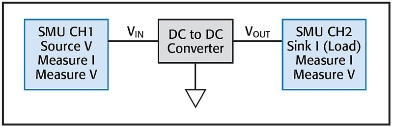
Figure 1. The use of one SMU channel on the input terminal and another on the output terminal replaces several instruments.
In today’s fast paced world of electronics design, complexity represents evil and must be avoided at all cost while simplicity represents all that is right and good. Ok, maybe it’s not quite that extreme, but when it comes to test and measurement, simplicity is the engineer’s best friend because it saves ti
. . . Learn More
Date:
08/01/2018
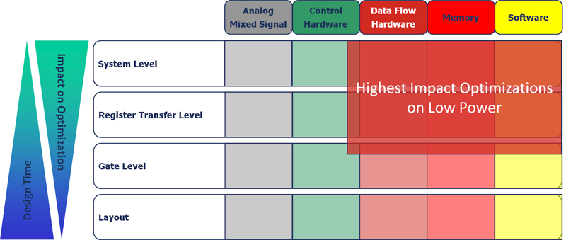
Figure 1 – Highest optimization potential exists at the system-level
Traditionally the key concerns and optimization targets in chip development have been summarized as “PPA”—performance, power and area. Depending on the application domain, the relative weighting of those three design objectives can vary greatly. In mobile devices, power has been key for quite some time. In
. . . Learn More
Date:
08/01/2018
