Click image to enlarge
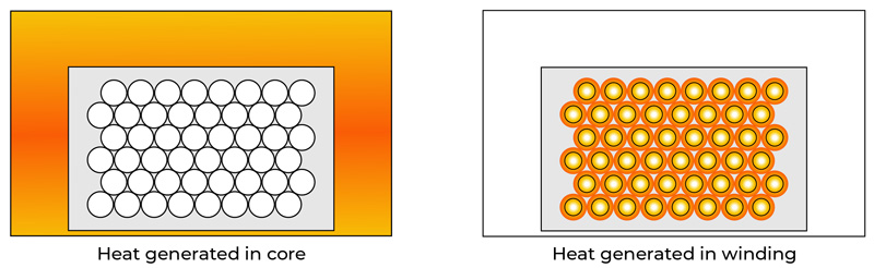
Figure1: Inductor Self-heating in the core vs the winding

Click image to enlarge
Figure 1: Half-cell diagrams of the N-Channel SJMOSFET (a) and N-Channel VDMOSFET (b)
Click image to enlarge
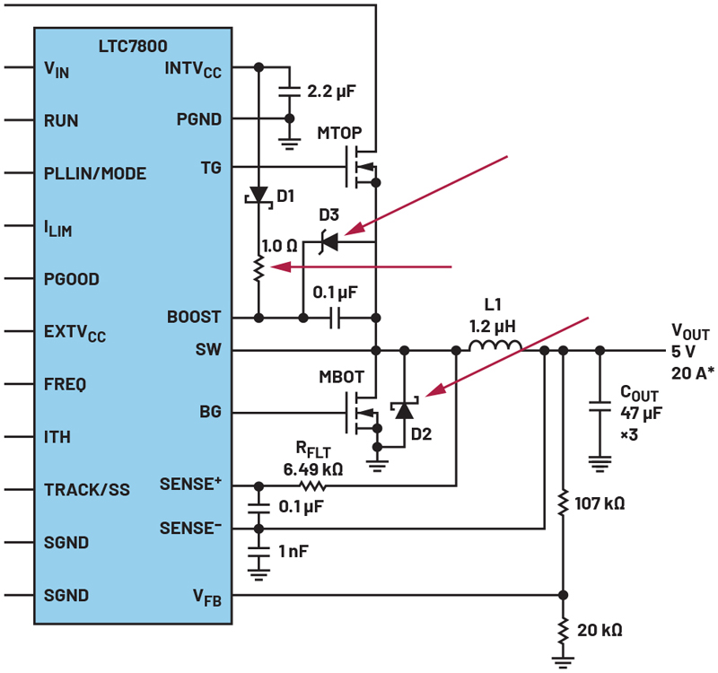
Figure 1. Necessary components to consider when using GaN technology as power switches in a power stage of the LTC7800 buck converter.
Click image to enlarge
Click image to enlarge
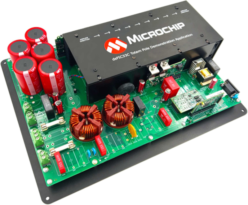
Figure 1: Totem-pole PFC demonstration application
Click image to enlarge
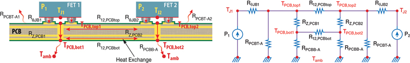
Figure 1: Cross-section view of GaN devices mounted on a PCB in a half-bridge configuration without a heatsink and the equivalent thermal circuit
Click image to enlarge
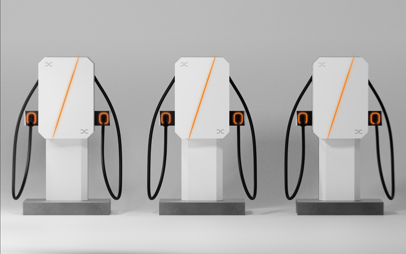
Figure 1: The new DC Authentix charger and modular site design enable rapid deployment of EV charging hubs for rideshare, robotaxis, and truck depots. Pre-configured components ensure fast assembly and operational readiness
Click image to enlarge
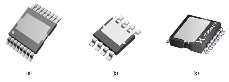
Figure 1: TOLT (a), PowerPAK 8x8R (b), and CCPAK1212i (c)

Click image to enlarge
Figure 1: Similarities and differences in the construction of polymer capacitors (Source: Kemet)
Click image to enlarge
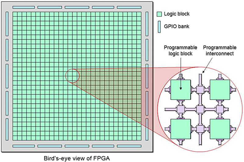
Figure 1: A Field Programmable Gate Array, or FPGA, is a type of integrated circuit (IC) that enables the development of custom logic for rapid prototyping and final system design. FPGAs are different than other custom or semi-custom ICs due to their inherent flexibility....