Technical Features

December 2021
DC/DC Flyback Converter

Click image to enlarge

Figure 1: Power stage of the flyback converter (simplified)

Isolated flyback converters often use optocouplers in the feedback loop to regulate the output voltage. As part of the compensation circuit, its parameters such as CTR influence the control loop and must be taken into account in the flyback converter design. The flyback converter is an isolated switching power
Date:
04/01/2024
AC or DC? Powering Intelligent Buildings

Click image to enlarge

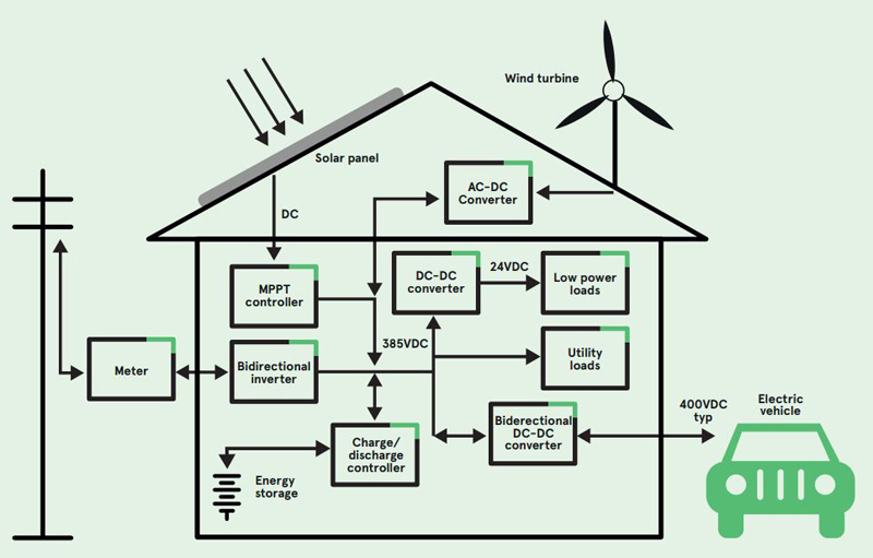
Figure 1: The DC-powered home

Most electronics requires DC at board level and even motor-driven AC machines are often ‘smart’, inverter-driven types, that operate internally from a high voltage DC bus. At the same time, buildings are becoming more ‘intelligent’ adding convenience, productivity and reducing energy consumption. This ca
. . . Learn More
Date:
12/01/2021

True Sustainability for Batteries

Click image to enlarge

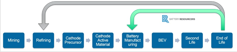
Figure 1: The efficiency of Battery Resourcers’ closed-loop approach

With the transportation and energy industries driving wide scale adoption of lithium-ion batteries, robust, scalable and reliable supply chains are becoming a priority for major vehicle OEMs, electric grid operators and even national governments. That’s the reason for the U.S. National Blueprint for Lithium Ba
. . . Learn More
Date:
12/01/2021
Empowering Next-Gen EV Fast Charging with Advanced Electrical Protection

Click image to enlarge

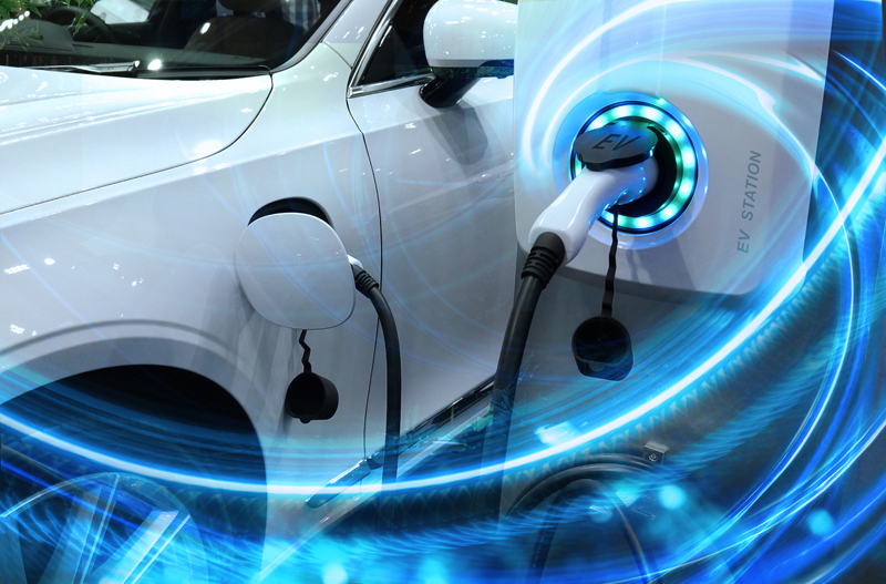
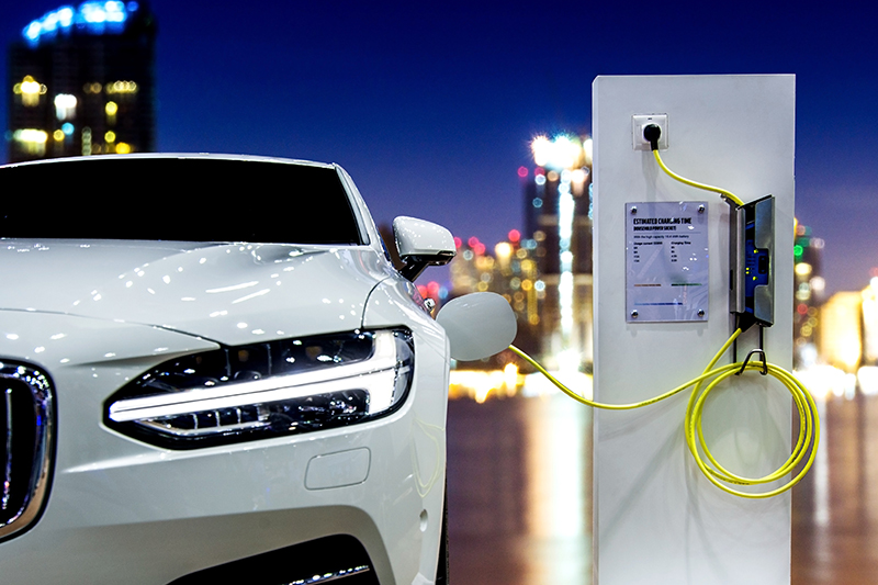
Figure 1: EV charging systems are migrating rapidly in the direction of DC-based 50kW to 350kW power solutions

Now that the latest Electric Vehicles (EVs) are exhibiting operational ranges satisfactory to the general public, the attention has shifted to battery charging times. These EVs are using the latest in wide-bandgap semiconductor solutions and power topologies, with system voltages often well over several hundred vo
. . . Learn More
Date:
12/01/2021
Meeting EMC Compliance Requirements Using Internal and External Filter Arrangements

Click image to enlarge

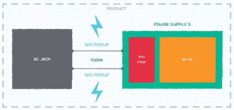
Figure 1: EMI pick-up in cabling

Among the most important of these specifications will be the ones that relate to electro-magnetic interference (EMI) and electro-magnetic compatibility (EMC). Having a good understanding of the EMI/EMC aspect of the chosen power supply will therefore be an essential part of its implementation. Furthermore, with bot
. . . Learn More
Date:
12/01/2021
Automotive Audio Bus and Ethernet in Automotive Applications

Click image to enlarge

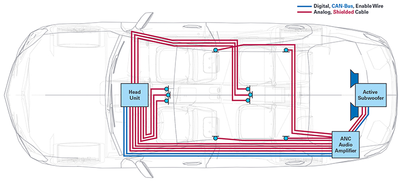
Figure 1. Traditional in-car cabling for audio systems

The number of electronic systems in cars has increased in recent years, reaching higher levels of complexity with the adoption of new technologies for infotainment and advanced driver-assistance systems (cameras, radar, lidar, etc.), along with multiple sensors for many different purposes (stability, speed, ac
. . . Learn More
Date:
12/01/2021
Charging Electric Commercial Vehicles

Click image to enlarge

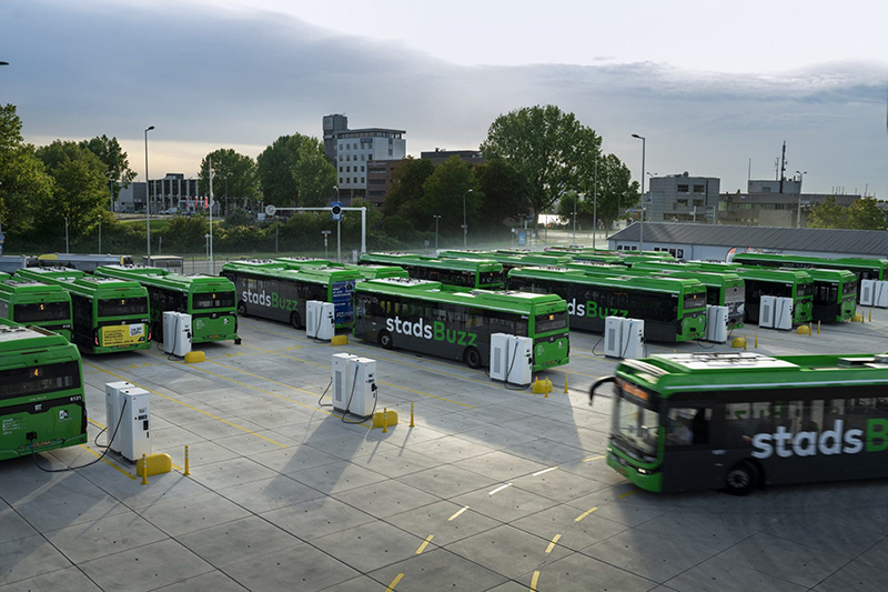
Figure 1. Modern bus depot with charging infrastructure

With the electrification of heavy-duty or commercial vehicles, charging larger batteries than the ones in electric passenger cars becomes necessary. As time is money especially in logistics, either assigning idle times for charging or increasing charging power are preferred options. This leads to three different ch
. . . Learn More
Date:
12/01/2021
EV Wireless BMS: Your Questions Answered
With Strategy Analytics estimating 36 million EVs on the road by 2026, wireless BMS offer promising ways to make vehicles more efficient and reliable – features that appeal to both original equipment manufacturers and consumers. For consumers, wireless BMS could potentially mean lower EV costs, along with be
. . . Learn More
Date:
12/01/2021
Silicon Carbide Modules Unlock Higher Power Density in Motor Drives

Click image to enlarge

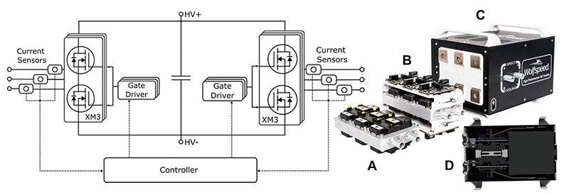
Figure 1: The system block diagram (left) showing three main components: the two converter modules, each with a gate driver, and the controller. The power modules mounted on the cold plate (A), and then in the power core with gate drivers (B), are also shown outside the dual inverter enclosure (C). Handles and feet are provided for portability, (D) shows the 204 mm x 267.5 mm cross section

The traction drive is where nearly all of an electric vehicle’s (EV’s) energy is put to use. The drive system must, therefore, perform with the highest possible efficiency while occupying the smallest possible space with the lowest weight — all to maximize the EV range. With the use of dual drives to enhance tr
. . . Learn More
Date:
12/01/2021
Archives


-->