Designing with digital power for optimum system performance
High efficiency and auto compensation benefit applications with large dynamic load currents
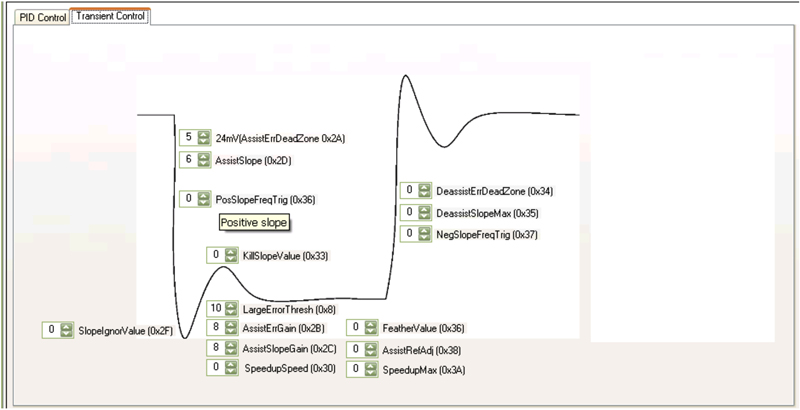
Figure 1: Optimising transient response parameters via a digital-power GUI.
Digital power has emerged to satisfy the need for power supplies capable of handling the complex and rapidly changing power demands of high-performance computing subsystems. These include equipment for applications such as internet or telecom switches, enterprise servers, data-centre equipment, and graphics workstations. A typical application using digital power consists of one or more high-performance processors, FPGAs or ASICs, along with DDR memory and multiple I/O ports. The key processing and memory components in the subsystem may require multiple VRs (voltage regulators), some of which may need specialised digital interfaces such as VID (Voltage Identifier), I2C, or Power Management Bus (Digital Power Technology). When designing the power supply, the effects of factors such as interactions and interdependencies between chips, sequencing issues, and power management must also be taken into account. In addition, the latest nanometre-scale IC process nodes demand lower operating voltages and greater precision in terms of accuracy, temperature stability, and transient response. Faced with such challenges, established analogue control techniques can struggle to maintain continuous, tightly regulated power as load currents change continuously and rapidly over a wide range. Designers working with conventional power supplies must also contend with time to market pressures that typically demand greater focus on the system design rather than the power supply. Limitations on PCB real estate also compromise designers' ability to optimise the power supply layout for minimum susceptibility to noise. Digital power controllers can overcome these challenges and enable a smaller implementation than conventional controllers can. They do so while offering powerful capabilities such as dynamic adjustment, adaptive response, and auto compensation to help maintain stable power across the spectrum of operating conditions. In addition, the online design tools for configuring this new generation of devices allow designers to collect real-time performance and diagnostic information from the controller on the customer's board. Design Approaches Engineers may design traditional analogue regulators using a spreadsheet, engineering calculation software such as Mathcad, or even paper and pencil. Typical design support for digital power controllers, on the other hand, integrates all tools within a single GUI. This significantly speeds up the design cycle and can improve the quality of the design, for example by plotting frequency response to aid stability analysis and allowing quick and accurate comparison of multiple simulations for easy optimisation. The GUI is not only used for setting the parameters and designing the application, but can also be used to monitor the controller's status in real-time when it is operating on the customer's board. Input voltages and currents, output voltages and currents, and temperature all report dynamically, including individual phase currents. Fault status is also available, making identification and debug much faster. With demand for extra channels and greater functionality within established form factors, designers effectively have less PCB real estate available for placing power components. It is increasingly difficult to achieve an optimal layout using traditional power topologies. Digital power, on the other hand, requires fewer components, and layout is less critical since the design is inherently more noise tolerant. Designers can also gain the advantages of reduced BOM (Bill of Material) costs for external components, and can change design parameters by updating software rather than having to change a component on the board. The update executes via a connection such as I2C or Digital Power Technology, which can be used to monitor the controller's status. Often, inventory data such as model number, revision number, and manufacturer identification is available for read back. Transient Response Digital power delivers critical performance advantages by allowing the use of non-linear control algorithms in addition to the proven linear control techniques used in analogue power regulators. Non-linear control can allow optimisation of many parameters affecting different parts of the transient response (figure 1).
The designer may choose to use standard linear voltage-mode control during steady-state conditions and small transients, and apply a non-linear ATA (adaptive transient algorithm) for the duration of any large transient events. The ATA is a non-linear closed-loop technique that uses the magnitude and slope of the monitored error signal to predict the current step and control pulse width and phase relationships accordingly. The power supply will typically operate in this mode for less than 10 μs and only during large transients. The designer can control the ATA through the GUI used for device configuration and monitoring. The designer can also optimise different parts of the response easily using graphical tools.
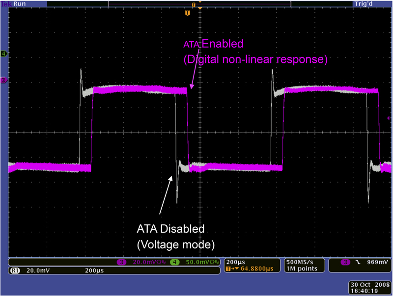
In figure 2, the grey waveform shows a digital power controller using only linear voltage-mode control. Overshoot and undershoot spikes are easily visible as the load steps on and off. The pink waveform shows how non-linear control effectively eliminates the undershoot and overshoot spikes under the same load-stepping conditions. Optimising Efficiency Digital power control enables designers to improve efficiency throughout the load range, from energy-saving standby modes to full power. It accomplishes this in part by using dynamic phase control with digitally scaled compensation to add or shed phases to satisfy varying system demand.
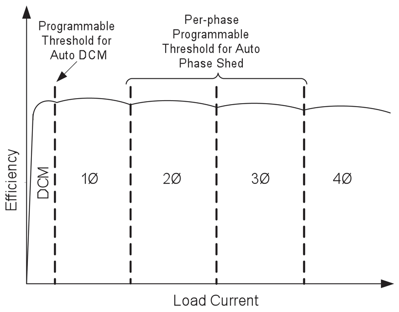
Analogue multi-phase voltage regulators typically allow two efficiency modes: with all phases turned on efficiency is good at maximum current, while single-phase operation is used to optimise efficiency at minimum current. Efficiency is less than optimal, however, in medium-current ranges. A digital controller is able to support preset phase-add and phase-drop points to ensure the optimum number of phases is active at a given output current level. In a 4-phase regulator, for example, drop points can be programmed to allow 1-, 2- ,3-, or 4-phase operation depending on load current (figure 3). The key challenge in implementing dynamic phase control lies in adding phases. Whereas the controller can drop phases relatively easily and rapid response is generally not critical, phases must add quickly in response to a sudden increase in the load. A good digital power controller must add phases extremely quickly—in the nanosecond range—and must add the phases in the right sequence and timing to ensure that the output voltage does not undershoot below specification. Phases add based on the slope or magnitude of the error signal, which enables near-instantaneous response. It is important to remember that a load oscillation could cause the controller to continuously add and drop phases. Under a load oscillation, it is better to keep more phases running to minimise disturbance at the output. Controllers can achieve this using a phase-drop filter with a preset limit such as 1.25 kHz and several Amperes of hysteresis to prevent spurious phase dropping during fast transients and to guard against phase bouncing.
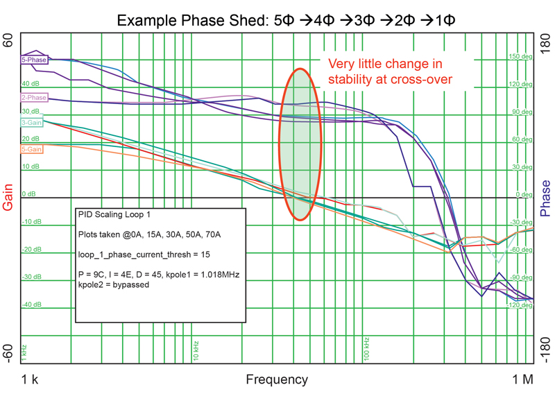
It is also important to remember that adding or subtracting phases changes the operating conditions and, hence, the stability of the control loop. A digital controller can calculate and store all the different compensation parameters for each operating condition and apply them appropriately to ensure stability of operation. Figure 4 shows how a five-phase controller essentially operates at the same stability point (cross over frequency and phase margin) irrespective of the number of phases running. International Rectifier


