Measure VSWR to quantify transmission-line imperfections
Simple measurements provide insight into transmission efficiency
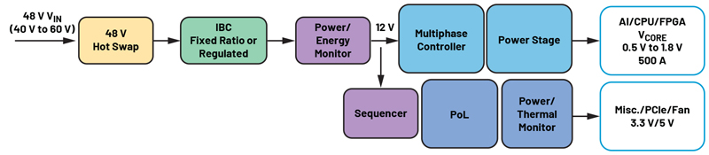
Figure 1: Transmission line circuit illustrating the impedance mismatch boundary between the transmission line and the load. Reflections occur at the boundary designated by ?. The incident wave is V+ and the reflective wave is V-.
Impedance mismatches in an RF transmission line causes power loss and reflected energy. The VSWR (voltage standing-wave ratio) is a way to measure transmission line imperfections. In an RF electrical transmission system, the SWR (standing-wave ratio) is a measure of how efficiently RF power transmits from the signal-power source, through the transmission line, into the load. A common example is a power amplifier connected through a transmission line to an antenna. The SWR is, thus, the ratio between transmitted and reflected waves. A high SWR indicates poor transmission-line efficiency and reflected energy, which can decrease transmission efficiency and damage the transmitter. Since the SWR commonly refers to the voltage ratio, RF engineers usually refer to it as the VSWR. VSWR and system efficiency In an ideal system, 100% of the energy transmits from the power stages to the load. This requires an exact match between the source impedance, that is, the characteristic impedance of the transmission line and all its connectors, and the load's impedance. The signal's AC voltage will be the same from end to end since it passes through without interference. In real systems, however, mismatched impedances cause some of the power to reflect back toward the source, like an echo. Reflections cause constructive and destructive interference, leading to peaks and valleys in the voltage at various times and distances along the line. VSWR measures these voltage variances. It is the ratio of the highest voltage anywhere along the transmission line to the lowest voltage. Since the voltage does not vary in an ideal system, its VSWR is 1.0 or, as commonly expressed as a ratio of 1:1. When reflections occur, the voltages vary and VSWR is higher, for example 1.2, or 1.2:1. Reflected Energy When a transmitted wave hits a boundary such as the one between the lossless transmission line and load, some energy will transmit to the load and some will be reflect back to the source (Figure 1). The reflection coefficient relates the incoming and reflected waves as:

where Vâ€" is the reflected wave and V+ is the incoming wave. The VSWR relates to the magnitude of the voltage reflection coefficient, ?, by:

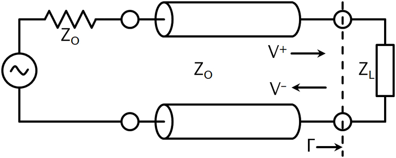
An SWR meter can directly measure VSWR . An RF test instrument such as a VNA (vector network analyzer) can measure the reflection coefficients of the input port, S11, and the output port, S22. S11 and S22 are equivalent to ? at the input and output port, respectively. The VNAs with math modes can also directly calculate and display the resulting VSWR value. You can calculate the return loss at the input and output ports from the reflection coefficient, S11, or S22 as follows:
Calculate the reflection coefficient from the transmission line's characteristic impedance and the load impedance as follows:

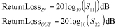
where ZL is the load impedance and ZO is the transmission line's characteristic impedance. You can also express VSWR in terms of ZL and ZO . Substituting eq 3 into eq 2,

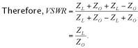

As noted above, VSWR is a specification given in ratio form relative to 1, as an example 1.5:1. There are two special cases of VSWR, ?:1 and 1:1. A ratio of infinity to one occurs when the load is an open circuit. A ratio of 1:1 occurs when the load matches perfectly to the transmission-line characteristic impedance. The VSWR definition from the standing wave that arises on the transmission line itself is:

where VMAX is the maximum amplitude and VMAX is the minimum amplitude of the standing wave. With two super-imposed waves, the maximum occurs with constructive interference between the incoming and reflected waves. Thus:

for maximum constructive interference. The minimum amplitude occurs with deconstructive interference, or:

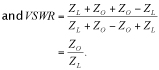
Substituting eq 5 and eq 6 into eq 4 yields

Substitute eq 1 into eq 7, we obtain:

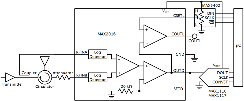
which matches eq 2, above. VSWR Monitoring System Modern RFICs simplify VSWR measurements. For example, the MAX2016 is a dual logarithmic detector/controller that, with a circulator and attenuator, can monitor the VSWR and return loss of an antenna. The MAX2016 outputs the difference between the two power detectors. The MAX2016 in combination with a digital potentiometer, such as the MAX5402, and ADC, such as the MAX1116/MAX1117, forms a complete VSWR monitoring system (Figure 2). The digital potentiometer acts as a voltage divider by using the MAX2016's reference voltage output. The internal reference voltage can typically source 2 mA. This voltage sets the threshold voltage for the internal comparator (pin CSETL). The MAX2016 can generate an alarm when the output voltage crosses the threshold (pin COUTL). The MAX1116 ADC requires a 2.7 to 3.6 V supply, while the MAX1117 ADC requires 4.5 to 5.5 V. The ADC can also use an external reference voltage, provided by the MAX2016. The ADC paired with the microcontroller allows for constant monitoring of the antenna's VSWR. Maxim Integrated