
The stability of data centers, telecommunication hubs, and server rooms is essential to the operation of companies, putting the onus on a strong power backup system
Figure 1: BBU shelf configuration in an OCP ORV3 architecture
Backup battery shelves play a key role by serving as the foundation of these systems, acting as the basis hub for the efficient storage of battery backup units (BBU) and creating a link that increases the readiness of critical power reserves. Their primary goal is to accommodate and manage up to six BBU modules, each aligned to house lithium-ion batteries paired with power converters. The architecture of these shelves has been adjusted, merging space use efficiency with accessibility, allowing for streamlined maintenance and simple replacement operations.
One of the key benefits of these battery backup shelves is the centralization and organization of BBU modules inventory. The availability of a defined storage system allows for easy tracking, labeling, and maintenance of BBU modules, reducing the danger of misplacement or confusion, especially in crucial situations. Furthermore, this centralized hub has shown to be a true benefit for battery health monitoring. This structure makes regular inspections, tests, and replacements easier.
The varied assortment of sizes and configurations of BBU shelves have been fitted to the individual requirements of varying industries and institutions. The modular design of certain shelves provides flexibility, allowing for future development in power demands. Meanwhile, these shelves contain integrated monitoring systems that provide real-time battery status information. Details such as voltage levels, temperature, module activities, and remaining capacity are displayed at a glance.
BBU Shelf Overview
As defined by the OCP for its new architecture for ORV3, the open rack power architecture consists of a centralized scalable power shelf and a BBU shelf that distributes power over a common busbar to pay load devices. This spec will define the BBU shelves that fit into the Open Rack. The BBU shelf will contain six BBU modules with 5+1 redundancy to provide DC power to all payloads within the rack. When an AC power outage occurs, the BBU shelf can provide backup power up to the maximum rating of the power shelf for a specified backup timeperiod. BBU shelf backup time allows the rack to be moved between power sources without interrupting IT gears and permits draining or moving applications before power is lost.
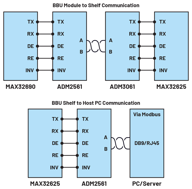
Shelf Microcontroller Firmware
The shelf microcontroller used in the BBU application is the MAX32625, an ultra-low power Arm Cortex-M4 microcontroller, which is responsible for communicatingtothehostcomputerviaModbusprotocol, communicatingtothe modulesviaModbus protocol, handling periodic charging of modules and systemcontrolmodes
Click image to enlarge
Communicating to the Host Computer
In Figure 2, the shelf microcontroller performs a critical role in establishing communication with the host computer over the RS-485 interface by acting as an expert Modbus server. Its primary function is to collect data from numerous modules in real time. This accumulated data is then delivered to the host computer, where it is used to populate a dynamic GUI application, providing a visually enhanced depiction. When communications are received from the host computer, the shelf microcontroller acts as a gatekeeper, authenticating the validity and integrity of each message. When the microcontroller is satisfied with the message’s authenticity, it quickly formulates its answer, drawing on the amount of information stored in the holding registers. This response contains the answers needed by the host computer, presented in a structured fashion.
However, the shelf microcontroller does not fail when the incoming message is polluted by anomalies. It quickly assumes the role of an effective communicator, responding with an error message based on the Modbus protocol. This error notice alerts the host computer to the abnormality, allowing appropriate corrective actions to be taken.
Communicating to the Modules via Modbus Protocol
In Figure 2, the microcontroller coordinates a complex and efficient communication ecosystem. When interacting with many BBU modules, it plays the role of a Modbus client, initiating and maintaining talks with each unique module. These BBUmodules act as Modbus servers, continuously updating their holding registers with the most up-to-date information. The shelf microcontroller embarks on a cyclical journey while operating in synchrony. It traverses the BBU module environment, capturing telemetry data from each module. This data is stored within the microcontroller’s memory, ready to answer should a question from the host computer arise.
However, the shelf microcontroller’s purpose is not limited to client-server interactions within the BBU system. It transforms into a Modbus server, delivering the collected data to the host computer upon request, creating a crucial bridge between the host computer and the numerous BBU modules. At the same time, it continues its function as a Modbus client, organizing interactions with the BBU modules and ensuring that the information is up-to-date and accurate.
Handling Periodic Charging of Module
According to the OCP requirements, a BBU module must be charged regularly because the battery pack leaks current while on standby. Because a BBU module can only be charged once every 10 days, the shelf microcontroller must monitor and manage which BBU modules will be charged. As a result, periodic charging is initiated by the shelf microcontroller, which uses a unique Modbus protocol command to determine which BBU modules require periodic charge. A basic necessity for the BBU modules within the system’s architecture derives from the OCP’s precisely developed standards. These modules, which are key components of the setup, must be charged on a regular basis. This requirement stems from the current leakage that the battery pack undergoes during standby periods. As a result, periodic charging becomes necessary to retain optimal performance and operational reliability.
System Control Modes
Finally, the OCP suggests adding a user control to override the BBU module operations. Through a Modbus, the user can adjust the operation of a single BBU to determine whether it requires charging or discharging.
Click image to enlarge
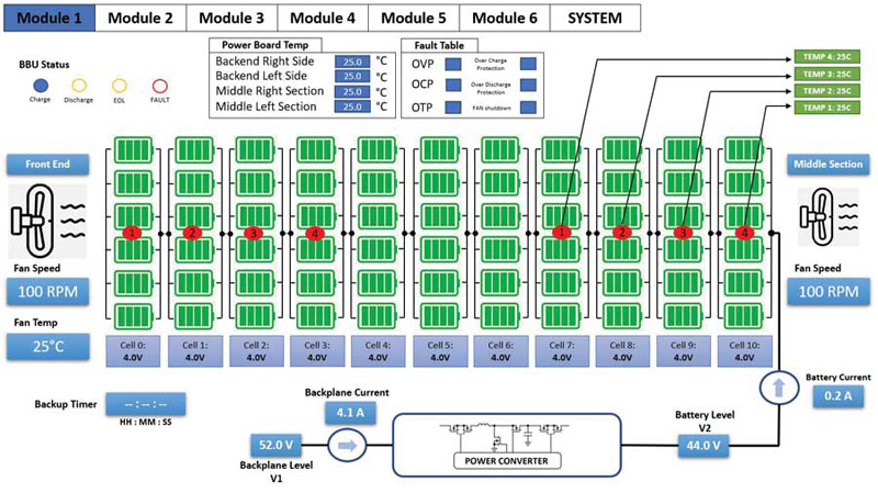
Figure 3: A BBU module
The BBU module GUI is divided into several sections that provide important information to the user. These components and functions are detailed in the following. See Figure 3.
Module Operation Status Indicator
On the GUI, thereare at leastfour LED indicators:
► The blue LED signals thatthe BBU module is in charge mode operation
► The first amber LED indicates that the BBU module is in discharge mode and providing backup power to the back plane of the data center
► The second amber LED indicates that the BBU module needs to be replaced and is in its end-of-life (EOL)
► The red LED provides information to the user that the BBU module is experiencing a fault
Module Internal Temperature Readings
Aside from the BBU operation status, the internal temperature of the module is also displayed in the GUI. At least nine temperature sensors are placed within the battery stack and power board. The LTC2991 provides digital temperature readings to the main MCU, while the ADBMS6948 provides analog battery stack temperature readings.
Module Fault Indicator Table
The GUI has a fault table that indicates different types of faults being triggered during the module operations, including overvoltage protection (OVP), overcurrent protection (OCP), over temperature protection (OTP), charge and discharge overprotection and FAN shutdown.
Power Converter Metrics
While the module is running, the GUI provides vital metrics for both the battery stack and the backplane. These metrics have a broad scope, encompassing crucial data such as input and output voltages as well as currents. This dynamic interaction between module operation and GUI provides users with a complete and real-time awareness of the system’s performance and energy dynamics.
Cell Information
The GUI displays the battery stack cell voltage and temperature level. This data is critical for determining the battery stack’s state of health (SOH) and state of charge (SOC).
Click image to enlarge
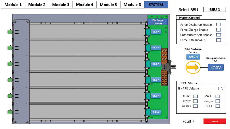
Figure 4: BBU modules summary GUI
Within the BBU module GUI, a window comprising both a brief summary and user control functionalities is present. This particular tab in the GUI furnishes the capacity to monitor all six BBU modules while affording individual control over a specific BBU, including the capability to enforce operational decisions (figure 4). Users can access the specified BBU modules by strategically selecting the precise BBU slot address. This strategic allocation is not random; it is a step aimed at preventing Modbus communication clashes, which is accomplished by predefining a set BBU shelf slot address.
Shelf System Control
By empowering users with the authority to modify BBU operations. They can prompt a specific BBU module to either charge or discharge over its operational span. Opting for the force discharge mode results in an elevation of the boost voltage from 48 V to 51 V, facilitating backplane power while maintaining the undisturbed operation of the power supply unit (PSU) within the data center. This nuanced control ensures an optimized balance between BBU functionality and the seamless running of the larger infrastructure.
Shelf Fault and Current Sharing
The summary table displays any faults detected on the six BBU modules and notifies the user. It is the quickest technique to locate any flaws in the BBU shelf. Furthermore, during BBU module parallel or redundancy operation, the current share bus indicator shows a bus voltage of 7 V when the backplane load is at its maximum and 10.5 V when peak load operation is in effect.


