24 GHz Radar Solutions Enable New Contactless Sensors for Emerging Industrial Mass Market
With the emergence of new sensor applications for RF radar comes a set of new development challenges
24 GHz, silicon-based millimeter wave radar technology is enabling a new generation of real-world, no contact smart sensors that are increasingly being used in mass market applications such as automotive, UAVs/ drones, broad industrial, and consumer.
These radar sensors provide real-time information such as an object’s presence, movement, angular position, velocity, and range from a few centimeters to several hundred meters from the sensor. Until recently, radar sensors at millimeter wave frequencies were realized using discrete solutions that were large in size, complex, and expensive to build, which limited broad industrial market adoption. New 24 GHz radar products from Analog Devices provide the performance and high integration levels that translate to low power, small size, low cost, and ease-of-use for applications such as object detection, tracking, security control, and collision avoidance warning systems.
Radar Sensor Development Challenge
With the emergence of new sensor applications for RF radar comes a set of new development challenges for many companies that want to quickly evaluate, design, and manufacture a radar sensor solution.
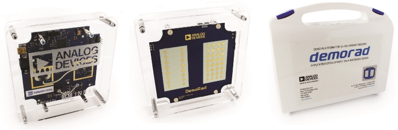
Acknowledging the challenges for companies that are motivated to develop RF radar as a sensing technology, Analog Devices recently introduced a 24 GHz radar system level prototype solution called Demorad (Figure 1), which enables application development hardware and software on a full system reference design. The 24 GHz radar Demorad system is a novel microwave radar evaluation platform with out-of-the-box software examples that enable the easy start-up of a radar sensor within minutes. Demorad enables the rapid product prototyping of radar sensor products that can measure real-time information such as target/object presence, movement, angular position, velocity, and range from the sensor.
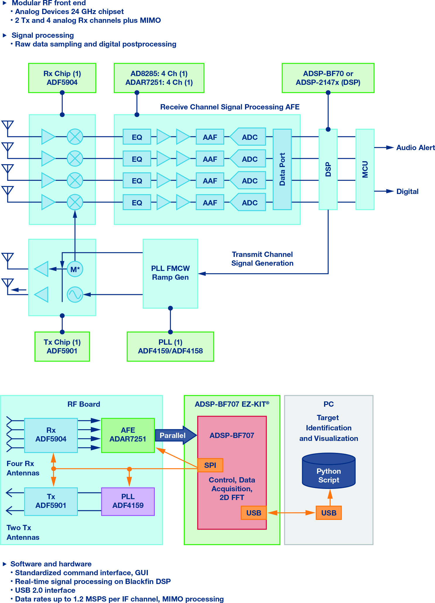
The system hardware solution includes RF antennas and a full RF to base-band signal chain, ADF5904 (receive), ADF5901 (transmit), ADF4159 (PLL), ADAR7251 (AFE), including ADI’s ADSP-BF707 DSP that quickly connects to a laptop/PC (Figure 2) with an easy to use, graphical user interface and radar algorithm software. Radar FFT and control firmware are available in the Blackfin DSP libraries. In a matter of a few minutes, users can plug the platform system into a computer with loaded software. Full software support of the 24 GHz radar IC using a software GUI and DSP radar sup-port function libraries are available with added capability to write raw data for postprocessing on a PC using MATLAB tools for radar sensor software design, such as 2D/3D radar FFTs, CFAR, and classification algorithms.
Click image to enlarge
Figure 2. Demorad RF to baseband signal chain and simplified block diagram.
FMCW Radar Basics
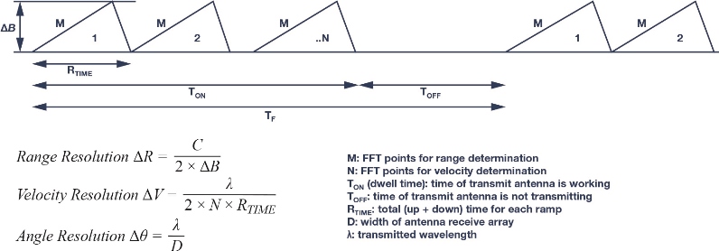
Shown in Figure 3, the frequency-modulated continuous wave (FMCW) radar ramp or chirp generation for radar transmit, and a set of important radar equations used to define the radar sensor design information.
Click image to enlarge
Figure 3. FMCW radar concepts.
The range resolution is dependent on transmit carrier sweep bandwidth—the higher the transmit sweep bandwidth, the higher the range velocity of the radar sensor. Velocity resolution depends on dwell time and carrier frequency—the higher the carrier frequency or the dwell time, the higher the velocity resolution. Angular resolution depends on carrier frequency—the higher the carrier frequency, the better the angular resolution.
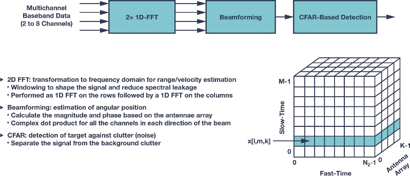
The Demorad radar system signal chain includes some basic algorithms in the DSP that are implemented for DSP FFT, beamforming, and CFAR. Basic target detection and target classifications are run on a host PC.
Click image to enlarge
Figure 4 describes the postprocessing of the captured data in the ADSP-BF707
Demorad is primarily designed for collecting radar signals in the time domain and frequency domain. The Demorad doesn’t include advanced target detection or object classification algorithms. This is an example of application-level development work that is generally carried out by the end system developer with a good knowledge of the environment that the radar sensor will be working in and the type of object detection that is required.
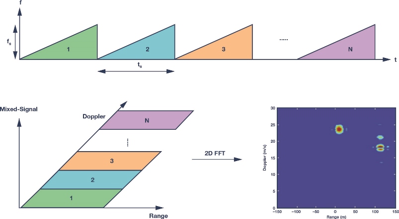
Shown in Figure 5 are some optimized 2D FFTs for the Blackfin ADSP-BF70x with an integrated window function, which helps avoid saturation, achieves higher SNR, and optimizes memory layout for higher bandwidth and more efficient data processing. Demorad offers different operation modes.
Click image to enlarge
Figure 5. Range and doppler frequencies using 2D Fourier transform.
FMCW Radar Mode
In FMCW mode, the distance to stationary targets can be measured. The frequency of the downconverted receive signal for a target is proportional to the distance to the target. In the GUI, FFT processing can be carried out to determine the frequency. Using the range-time display option makes it possible to view moving targets, while the display stores a number of FMCW sweeps.
Range Doppler Mode
In range doppler mode, the range to the targets, as well as the speed can be analyzed. Range doppler mode is one of the most powerful modes of operation because of its ability to process multiple transmit ramps or chirps simultaneously by evaluating a two-dimensional Fourier transform. The range doppler processed data is displayed in the range doppler map. Range doppler is powerful in that it allows a separation of targets with different velocities, even if they are located at the same distance. This is useful for multiple fast moving targets in different directions— for example, to resolve complicated traffic scenarios with cars moving in opposite directions or during overtaking manoeuvres.
Digital Beamforming (DBF) Mode
In DBF mode, the distance and the angle to the target are displayed. The receive signals from the four receive channels are used to estimate the angle of the target. The display shows spatial distribution of targets in the xy-plane. In DBF mode, the system is configured the same as in FMCW mode but with different processing of the IF downconverted signals. After calculating the range, the angle information of the target is calculated by evaluating the phase differences between the four receive channels. In DBF mode, a radar front-end system calibration is required to eliminate unwanted deterministic phase variations between the receive channels. Each Demorad system comes with factory calibration data that is loaded when the GUI is run. The sampled IF signals are then corrected before evaluating the sensors’ measured data.
The Demorad platform utilizes MIMO operation by using the two transmit outputs available on the ADF5901 and appropriate antenna placement. This yields seven receive channels to increase the angular resolution of the sensor—for example four real receive channels and four virtual receive channels with overlap on one channel. The waveform used in Demorad utilizes the fast ramp feature of the ADF4159 PLL with an up chirp of 280 µs and down chirp of 4 receives for a total ramp period of 284 μs. 256 samples are taken or data sampled in the up ramp with the ADAR7251 AFE ADCs running at 1 MSPS.
The Demorad uses FMCW radar to detect range and velocity of objects up to 200 meters away with a resolution of approximately 75 cm. The field of view (FOV) is approximately 120° in azimuth and 15° in elevation, based on the antenna array design. By combining antennas as used in digital beamforming (DBF) Demorad uses DBF to calculate angular information in the FOV.
.jpg)