Author:
David Megaw, Senior Design Engineer and Bruce Haug, Product Marketing Manager, Analog Devices
Date
05/30/2022
 PDF
PDF
Click image to enlarge
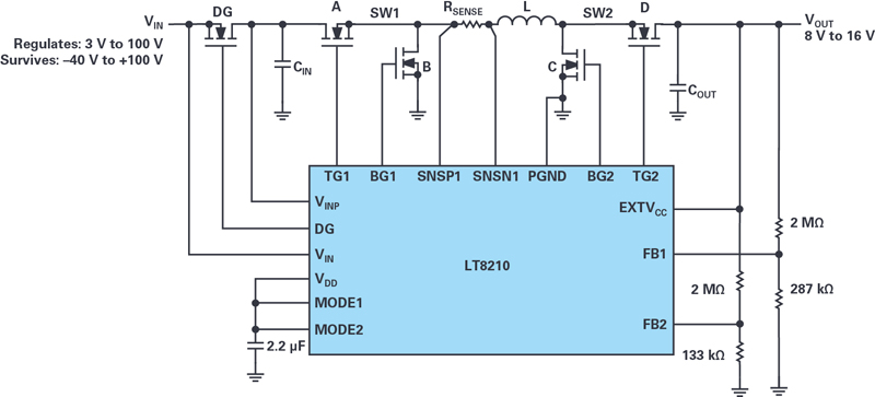
Figure 1. LT8210 8 V to 16 V Pass-Thru regulator circuit.
A common dc-to-dc converter problem is generating a regulated voltage when the input voltage can be above, below, or equal to the output—that is, the converter must perform both step-up and step-down functions. This scenario is typical when powering vehicle electronics from a nominal 12 V battery, which can vary from engine cold crank (down to 3 V) and load dump (up to 100 V), or a reverse battery voltage from operator error. There are several dc-to-dc converter topologies that can perform both step-up and step-down operations, from SEPIC to 4-switch topologies, but none of these solutions pass the input voltage directly to the output without actively switching—until now, that is.
The LT8210 is a synchronous buck-boost controller that can operate in Pass-Thru mode, which eliminates EMI and switching losses, and maximizes efficiency (up to 99.9%). Pass-Thru operation passes the input directly to the output when the input voltage is within a user programmable window. The LT8210 operates over an input voltage range of 2.8 V to 100 V, allowing it to regulate from the minimum input voltage during cold crank to the peak amplitude of an unsuppressed load dump. The LT8210 can operate as a conventional buck-boost controller with pin-selectable continuous conduction mode (CCM), pulse-skipping, or Burst Mode operation, or in a new Pass-Thru mode in which the output voltage is regulated to a programmed window. When the input voltage resides in this window it is passed directly to the output without actively switching the FETs, resulting in ultralow IQ operation and the elimination of switching noise.
Pass-Thru Operating Mode
Figure 1 shows a simplified schematic of an LT8210 configured for Pass-Thru operation with the output regulated to be between 8 V and 16 V. The top and bottom voltages of the Pass-Thru window are set by the FB2 and FB1 resistor dividers, respectively.
Click image to enlarge
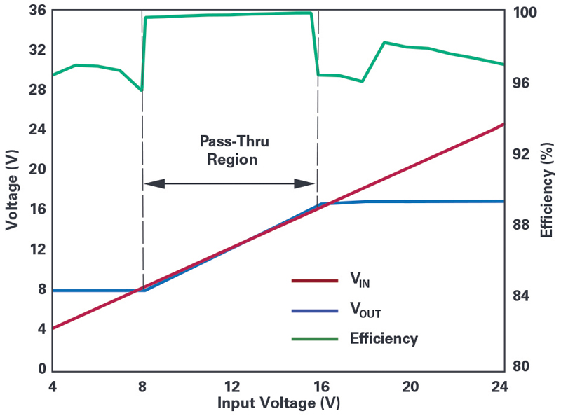
Figure 2. Pass-Thru operation enables 99.9% efficiency in the Pass-Thru input voltage window.
Figure 2 shows the input/output transfer characteristic of this circuit. When the input voltage is above the Pass-Thru window, the LT8210 steps it down to a regulated 16 V output. If the input voltage drops below the window, the LT8210 boosts to maintain the output at 8 V. When the input voltage is within the Pass-Thru window, the top switches, A and D, turn on continuously, allowing the output to track the input and the part to enter a low power state with typical quiescent currents on the VIN and VINP pins of 4 µA and 18 µA, respectively. In this non-switching state, there are neither EMI nor switching losses, making efficiencies greater than 99.9% achievable.
Click image to enlarge
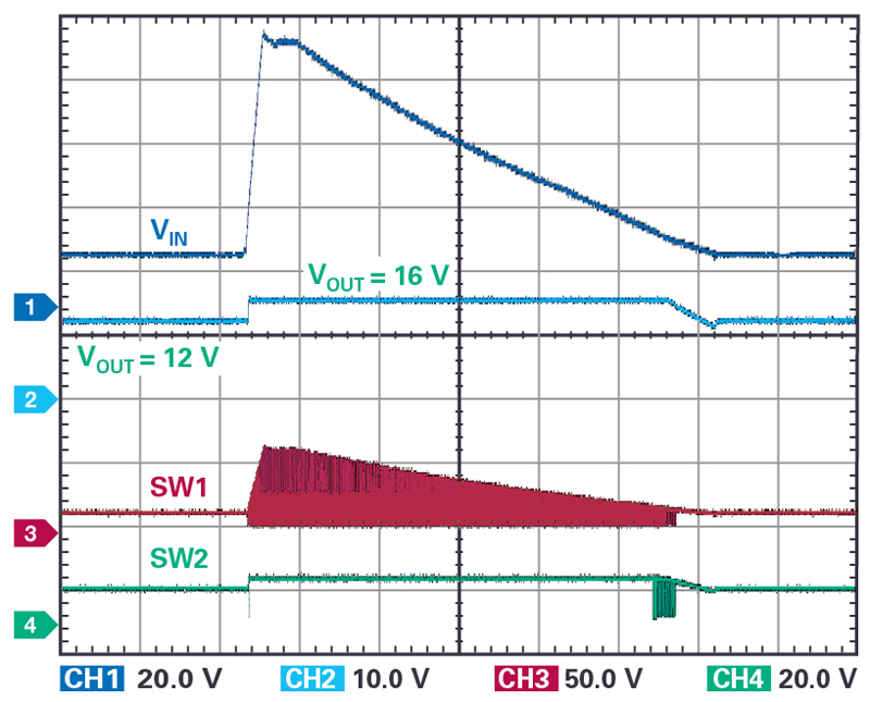
Figure 3. The LT8210 in Pass-Thru mode quickly responds to an 80 V unsuppressed load dump pulse, limiting the output to the programmed 16 V maximum.
Click image to enlarge
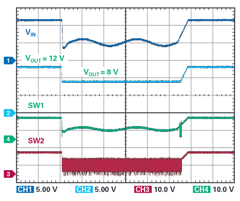
Figure 4. The LT8210 in Pass-Thru mode responds to a cold crank pulse (<4 V) by boosting to the programmed 8 V minimum output voltage.
Click image to enlarge
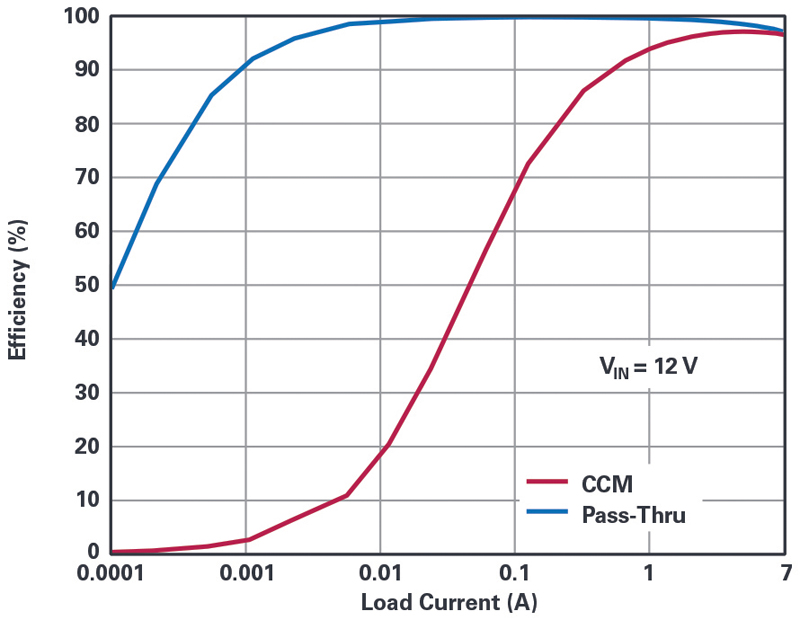
Figure 5. In the Pass-Thru region, efficiency reaches nearly 100%, compared to continuous conduction mode efficiency.
Click image to enlarge
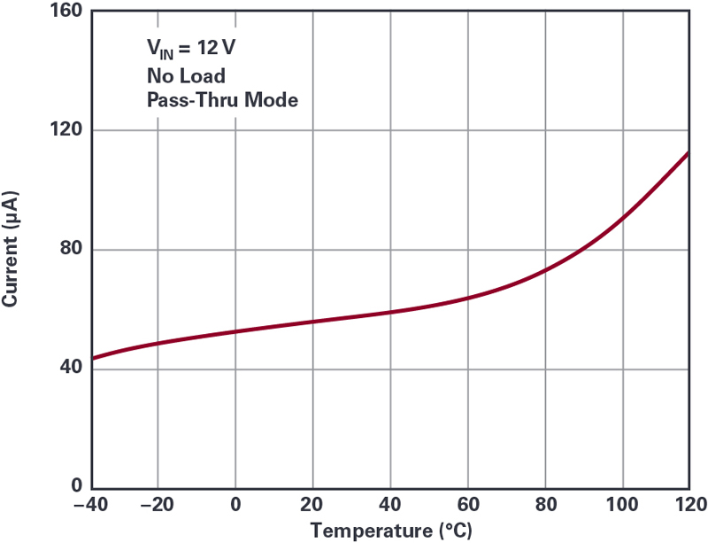
Figure 6. The LT8210 features ultralow quiescent current in the Pass-Thru region.
Conclusion
Automotive batteries and similar wide voltage range power sources are a complex problem for dc-to-dc converter designers, requiring protection features and buck and boost conversion at high efficiency. The LT8210 synchronous buck-boost controller eliminates complexity by combining protection features with a wide input range buck-boost converter and a unique Pass-Thru option. It operates over a 2.8 V to 100 V operating range with built-in reverse voltage protection. Its Pass-Thru mode eliminates switching losses and noise while achieving ultralow quiescent current. In Pass-Thru mode, the output voltage is not regulated in the conventional sense, but is instead bounded by a programmable voltage window.