60V Buck-Boost LED Driver with up to 98% Efficiency has Internal PWM Dimming & Spread Spectrum
Synchronous buck-boost converters with four power switches can deliver very high efficiency while providing both step-up and step-down DC/DC conversion. Combining the capabilities of two separate converters (buck and boost) has the advantage of reduced solution size and cost. Four-switch converters should be able to operate with just two switches for highest efficiency when only step-up or step-down conversion is needed. However, they must also be able to utilize four-switch operation as VINand VOUT approach each other, and to transition gracefully between these regions of operation. Combining control loops for two-switch boost, two-switch buck, and four-switch operation, and designing nearly flawlessly transitions between these regions of operation has its challenges. However, the next generation of buck-boost converters masters these challenges and more.
The LT8391 60V four-switch buck-boost LED driver is designed to drive high power LEDs up to 250W and to flawlessly transition between two-switch boost, four-switch buck-boost, and two-switch buck regions of operation. A patent pending four-switch buck-boost current-sense resistor control scheme provides a simple, yet masterful method for the IC to run in peak current mode control in all regions of operation with a single sense resistor. This new generation buck-boost LED driver features spread spectrum frequency modulation and internally generated PWM dimming, which work together. The LT8391 has flicker-free PWM dimming with both internal and external PWM dimming, even when spread spectrum is turned on (another patent pending technique).
98% Efficient Buck-Boost LED Driver
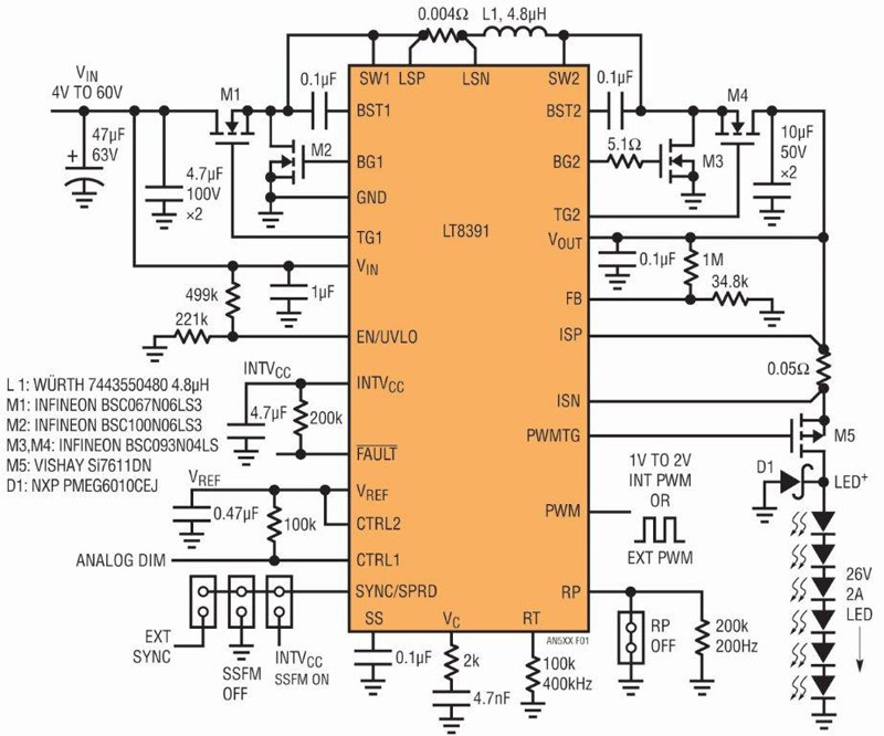
The LT8391 high power buck-boost LED driver in Figure 1 drives 25V of LEDs at 2A from a wide input voltage range. Efficiency can reach 98% at its highest point.
Click image to enlarge
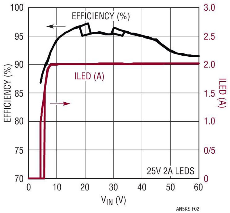
Figure 1. LT8391 4V to 60V Four-Switch Synchronous Buck-Boost LED Driver Powers a 25V 2A (50W) String of LEDs at up to 98% Efficiency.
Over the typical automotive battery range of 9V to 16V, the converter operates between 95% and 97% efficiency. With a single high power inductor, the temperature rise is low, even at 50W. At 12VIN, no component rises more than 25°C. At 6VIN, the hottest component rises less than 50°C with a standard 4-layer PCB and no heat sink or air flow. This leaves room to increase the power output of the converter, making hundreds of watts possible.
Click image to enlarge
Figure 2. (a) The Efficiency of Figure 1 50W LED Driver Has a Peak of 98% and Ranges from 95% to 97% Throughout the Typical 9V to 16V Automotive Input Range.
Click image to enlarge
Figure 2. (b) The LT8391 Peak Inductor Current Limit Can Maintain Stability with Reduced Output Power at Low VIN.
The LT8391 operates down to 4VIN, where IINcan get very high. The LT8391 is designed to either handle very high input currents or use its peak switch current limit to operate with stability at low VINwhile reducing output power. This allows the converter to run through automotive cold-crank voltages or other drops in VINwithout an increase in power component size or cost.
The LT8391 can achieve 1000:1 PWM dimming with no flicker. The high side PWM (TG) MOSFET PWM dims a grounded LED string. It also acts as an overcurrent disconnect during short-circuits.
Internally Generated PWM Dimming
The LT8391 has both standard external PWM dimming and internally generated PWM dimming. LT8391’s unique internal PWM dimming eliminates the need for components such as clocking devices and microcontrollers to generate accurate PWM brightness control at ratios as high as 128:1.The IC’s internally generated PWM frequency, such as 200Hz, is set by a simple resistor on the RP pin. A voltage between 1V and 2V on the PWM pin determines the PWM duty cycle. The duty cycle of the internal dimming ischosen as one of 128 steps and internal hysteresisprevents duty cycle chatter. The <±1% accuracy ofinternally generated PWM dimming is the same forall regions of operation.
Spread Spectrum Frequency Modulation (SSFM) Reduces EMI
SSFM reduces EMI in switching regulators. Although the switching frequency is most often chosen to be outside the AM band (530kHz to 1.8MHz), unmitigated switching harmonics can still violate stringent automotive EMI requirements within the AM band. Adding SSFM significantly reduces EMI both within the AM band as well as other regions.
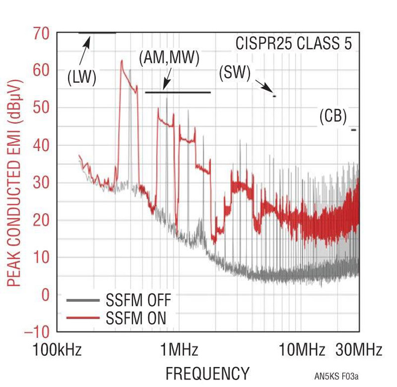
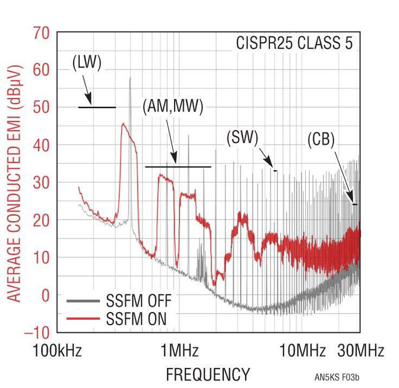
When activated, SSFM drops the LT8391’s 50W LED driver EMI below both the peak and average EMI requirements of CISPR25 (Class 5) in the AM band. CISPR25 average EMI limits are 20dBμV lower in some places than peak limits, and harder to pass for switchers. For this reason, LT8391’s novel SSFM reduces average EMI more than its peak. There is 18dBμV or more reduction of average EMI and about 5dBμV of peak EMI reduction.
Click image to enlarge
Figure 3. SSFM Reduces LT8391 Peak and Average EMI Below CISPR25 Class 5 Limits. Average EMI Has Even Greater Reduction Than Peak EMI.
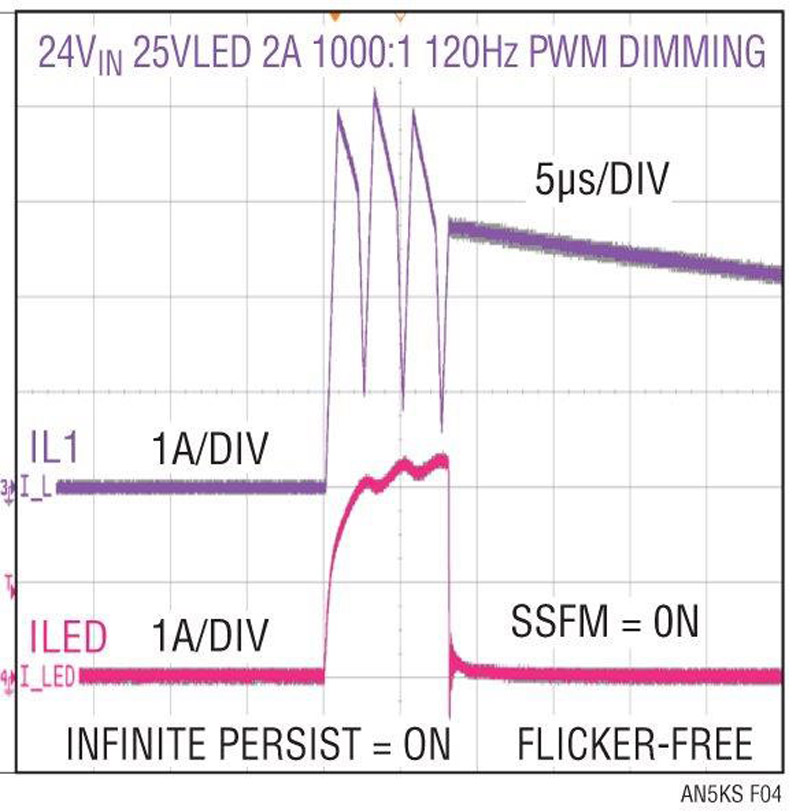
In some LED converters, SSFM and PWM dimming do not work together without causing flicker. SSFM, a source of changing switching frequency, may appear as noise to the outside world in order to spread EMI lower than its non-spread peak values, but it can work with PWM dimming for flicker-free operation. Linear’s patent pending PWM dimming and SSFM operation runs both functions simultaneously with flicker-free operation, even at high dimming ratios. At 1000:1 PWM dimming with external PWM and at 128:1 internally generated PWM, SSFM operates with flicker-free LED current.
Click image to enlarge
Figure 4. Infinite-Persist Scope Capture Shows Flicker-Free Dimming with PWM and SSFM Working Together.