A Bidirectional Power Solution for 48V Bus Conversions

Frederik Dostal from Analog Devices talks to PSD about the most efficient way to down-convert from the 48V bus.
The 48V intermediate bus is rapidly growing in popularity. The automotive market is moving quickly towards adopting it, data centres use it widely, the industrial market has it as standard and it is also extensively used in automated testing. 48V is seen as the optimal voltage level to sit between the mains or battery power source and the final component or subsystem, as a large voltage difference would be impossible to convert efficiently in a single stage. As with any conversion with multiple stages, losses are multiplicative, so efficiency is a priority, and the most efficient way to convert down from 48V is usually by using a charge pump. However, there is one problem with that. Normally charge pumps can only half the input voltage, and 24V is not really a voltage that is of use to many applications. However, the addition of a single inductor makes it possible to output a range of more desirable voltages.
Frederik Dostal, Subject Matter Expert for Power Management at Analog Devices explains, “we use charge pumps as the efficiency is super high. It can take a voltage of 48V down to 24V with a current of 2 or 3A at an efficiency above 99%. The problem is the output voltage is set at 24V, and the majority of applications need 12V, 5V, 3.3V or another lower voltage. For these applications, Analog Devices has developed a hybrid topology, which combines the benefits of the charge pump with a buck regulator. The lower set of two switches are used for both the charge pump and the buck converter. This allows 48V to be converted to 12V or lower in a single conversion stage at high efficiency by adding an inductor. The output voltage is set by a single resistor.”
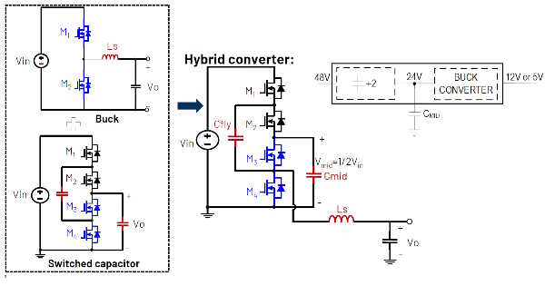
Figure 1 - The bottom two switches of the charge pump are also used as the two switches needed for the buck regulator
The whole system is integrated into the LTM4654 μmodule, which has power handling capabilities of up to 300W. Several LTM4654 devices can easily be combined with load sharing for higher power levels. The four switches in the circuit are thermally attached to the inductor, which acts as a heatsink and pulls the heat out of the switches. The device has also been optimized for EMI - a previous drawback of charge pumps is that they were electrically noisy at anything but very low currents. The complete EMI of the LTM4654 is below the most common EMI limits and meets all CISPR 22 standards. If a negative voltage is required, the LTM4654 can take an input voltage of around 30V and the internal charge pump can invert the voltage and then the buck regulator is used like an inverting buck regulator to generate the negative voltage, so that it outputs both negative voltage and current.
Dostal continues, “another nice aspect of the LTM4654 is that when there is a load that has a motor, or other high inductance load, that can turn off suddenly and generate energy, the module can both sink and source the current. That can be very useful as energy can then be stored in capacitors on the 48V bus. Another possible use for this type of module is battery conditioning, allowing the battery to charge and discharge. Whether the current is positive or negative, we see efficiencies between 96% and 97% for positive conversion and 95% to 96% for negative conversion.”