A Guide to the Fundamentals of Thermal Management
Investigating potential heat sources within an electronics-based application and highlighting various thermal management methods
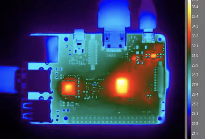
Figure 1: Thermal infrared image of a PCB showing significant heat sources. (Source: Teledyne Flir)
Electronic components like to run cool. Any part that exhibits an internal self-heating effect will reduce its reliability and those of others around it. The heat generated may also cause long-term warping of the PCB, potentially decreasing the integrity of connections to other components and impacting trace impedances. Typically, waste heat from power supplies and any form of power amplifier (audio or radio frequency (RF)) are the usual suspects, but modern systems-on-chips (SoCs), power conversion modules, and powerful microprocessors can also generate considerable internal heat.
Seeking Out Sources of Heat
Thermal management is a crucial aspect of electronic design, as it helps regulate the temperature of electronic devices and prevent damage due to overheating. Some electronic components generate heat from their routine operation, and if the heat is not adequately dissipated, it can reduce its overall lifespan or cause permanent damage. Thermal management aims to maintain safe operating temperatures for electronic components and ensure their long-term reliability and performance. The heat generated is considered an energy loss, indicating energy efficiency reduction. As we'll discover later in this article, dissipating heat involves various methods, from forced air cooling using a fan and convecting the heat away using a heatsink.
When considering thermal management, it is imperative to understand the safe operating temperature range for every component in the design. Datasheets typically provide this information, stating a range between lower- and upper-temperature limits, often termed the safe operating area (SOA). The SOA defines the range over which the component will operate reliably without unpredictable behaviour or premature ageing. Also, the ambient temperature the circuit will regularly work within is an important consideration.
Applications and components likely to generate unwanted heat include the following:
Power conversion: Power supplies converting line AC voltage to lower DC voltages will always incur some losses. The efficiency of a power supply typically varies depending on the load conditions and the converter topology. For example, the XP Power ASB160 160-watt AC/DC switch-mode power supply has a maximum full load power efficiency of 91% to 93%. This efficiency specification indicates that up to 9% of the 160 watts of line input energy (i.e., 14.4 watts) will require dissipation. The likely heat sources in a power supply include switching MOSFETs, diodes, and inductors.
Motor drives: The MOSFETs of high-power industrial motor gate driver circuits can generate significant unwanted heat. The final stage of semiconductors or integrated modules usually represents the primary heat sources, requiring heatsinks and other thermal components. The internal series resistance during the conduction of a MOSFET or other power semiconductor might be relatively small. Still, the heat generated can be considerable in high-current, high-voltage applications.
Passive component self-heating: Internal self-heating of passive components such as capacitors, resistors, and inductors is well understood. Although the amount of lost energy might be relatively small for each part, these components are widely used in large numbers, becoming a significant heat source.
Amplification: Any semiconductor or module-based amplification circuit will generate some amount of heat. Audio and RF amplifiers are the most likely candidates. The amplifier's efficiency and input power determine the maximum heat requiring dissipation. Some amplifier topologies are more efficient, so understanding the possible peak power and the amplifier’s operating efficiency across all use cases is essential.
PCB traces and interconnects: There is always the possibility that the impedance of PCB traces can generate heat during peak load conditions. The PCB trace width and layout should be calculated for the maximum operating conditions; otherwise, there is potential for localised heating, warping, and burning. Likewise, long-term excess loading of board interconnects can generate heat at the connector terminals, resulting in damage and, potentially, burning.
In addition to checking component datasheets for their safe operating temperatures and understanding the circuit parameters, a thermal camera (Figure 1) can provide an accurate image of the primary heat-generating components.
Heat Impact on Component Reliability
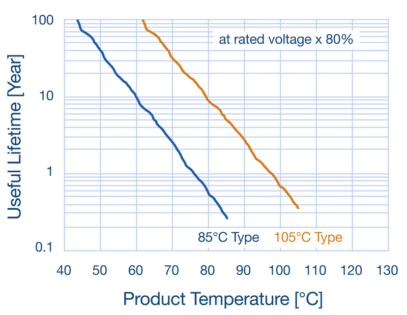
Elevated levels of heat can have a dramatic impact on component reliability. Figure 2 illustrates the predicted lifetime reliability of multi-layer ceramic capacitors (MLCCs) rated at + 85°C and + 105°C. For example, when operating at 50°C, the +85°C-rated MLCC has a useful lifespan of 40 years. This drops to just ten years when the average operating temperature increases by ten degrees to 60°C.
Click image to enlarge
Figure 2: The impact of temperature on MLCC life. (Source: Murata)
The reliability of any system is specified as the mean time between failure (MTBF) and is calculated based on component reliability parameters. Any increase in the average operating temperature due to excess heat will lower the unit's MTBF.
Also, many semiconductor devices and batteries exhibit thermal runaway. In this chain reaction phenomenon, current flows increase due to increases in temperature, resulting in an upward spiral that can result in component failure, system overload, and fire.
Thermal Management Techniques
There are several ways that heat dissipation occurs, including conduction and convection. Conduction is the transfer of heat (thermal energy) from one object to another. Drawing thermal energy from a hot component to a cooler object lowers the component's temperature. Conduction is the most effective heat transfer method since it requires the smallest surface area.
Convection cooling uses moving airflow to remove heat from an object, redistributing it into the surrounding air. As the air removes the heat, more air is drawn in, increasing the airflow and lowering the heat source's temperature. The airflow can occur naturally or can be forced; for example, the heat dissipation process accelerates when using a fan. Additionally, heatsinks increase the effective surface area of a component, improving the amount of heat dissipated.
Thermal Impedance and Thermal Interface Materials
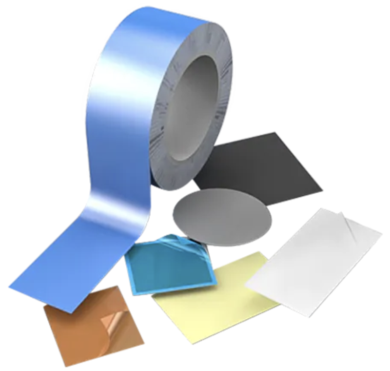
Thermal impedance measures a material's effectiveness at conducting heat and is an important parameter when assessing thermal management calculations. For example, thermal interface materials (TIMs) such as pads, gels, and pastes improve heat conduction between a power MOSFET. Some of these conduct heat but provide galvanic isolation between the materials. Würth Elektronik offers a wide range of thermal interface materials (Figure 3). Examples include the WE-TINS series, thin silicone pads designed to electrically insulate electronic components and cooling assemblies while allowing heat flow, and the WE-TGFG series, which incorporate a synthetic graphite layer wrapped around a foam core to provide a highly conductive, silicone-free heat-spreading alternative to fill vertical gaps.
Click image to enlarge
Figure 3: Some of the range of thermal interface materials available from Würth Elektronik. (Source: Würth Elektronik)
Panasonic also offers a range of thermal management solutions, such as the EYG-R graphite pads. These pads are easy to install and provide a high reliability characteristic and low thermal resistance because one side has a smoother surface, providing enhanced thermal contact. The Panasonic graphite pads feature high compressibility, effectively filling the voids between the heating and cooling devices for better heat transfer.
Heatsinks
Heatsinks come in all shapes and sizes. Many are designed for specific power semiconductors and IC/SoC packages. Others suit industry-standard modules, such as the ATS maxiFLOW series of heatsinks from Advanced Thermal Solutions Inc., designed for full-brick DC/DC converter modules.
CUI Devices also supplies a wide range of heatsinks suitable for semiconductor packages and modules. To assist with selection, CUI offers a heatsink selection guide.
Fans
Fans are employed to provide a forced flow of air across PCBs and heatsinks. Examples from CUI Devices include variable-speed DC centrifugal fans and DC axial fans, both featuring the omniCOOL bearing system.
Peltier Modules
A Peltier thermoelectric module can cool semiconductors and other small heat source components and is ideal for space-constrained enclosures. Discovered by Jean Peltier and a characteristic of the Seebeck effect, the application of a current flow through two different conducting materials results in the flow of thermal energy between them. Typically constructed using P-type and N-type semiconductor pellets, these compact modules offer an effective heat transfer from source to heatsink with no moving parts.
Figure 4 illustrates the flow of thermal energy between a source and a dissipating heatsink. CUI Devices supplies a range of standard and micro Peltier modules capable of accommodating temperature gradients as high as +77°C.
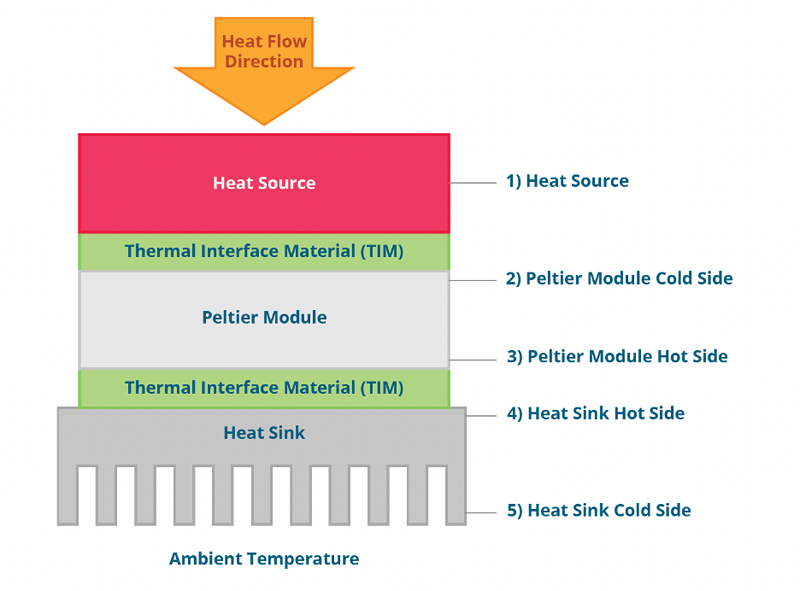
Click image to enlarge
Figure 4: The temperature gradient from a heat source to a heatsink using a Peltier module. (Source: CUI Devices)