The shift from discrete DC-DC converters to integrated power modules continues
As the shift from discrete DC-DC converters to integrated power modules continues, more complex devices are being introduced into the market for applications in several fields like industrial and telecommunications. These both require programmable modules with small footprints and high power density that deliver multiple rails. Programmability of output voltage levels, switching frequency and error trip levels combined with health monitoring and reporting through an SMBus Compliant - I2C interface; provide a high level of flexibility and above all a very high level of reliability.
The Challenge
The on-going push for smaller electronic equipment and appliances has resulted in power management applications that demand a wide range of specifications that dictate the use of multiple ICs and discrete components to meet all the requirements. Generally, these components are not perfectly matched for the application and hence some compromises must be made in the final design implementation. This also leads to larger PCB real estate to accommodate such designs leading to higher cost and potentially larger EMI due to trace parasitics ringing and ground planes bouncing in a larger size PCB.
Achieving good efficiencies is an absolute requirement to achieve higher reliability and lower PCB temperature rise; but this necessitates finding, sourcing and testing multiple power components like MOSFETs, MOSFET gate drivers, inductors and capacitors. This process can be a lengthy and costly activity and, once successful, next leads to the challenging task of PCB layout of the powertrain, which can take several iterations to reach an acceptable design. The lengthy process is a major investment in resources, time and cost that may affect time-to-market and/or the competitive positioning of the product.
In response to these requirements, Exar has just released the XRP9711, a new power module with two fully-integrated synchronous buck converters plus two controllers in a 12mm x 12mm x 2.75mm LGA package, offering best-in-class power density (see Figure 1). These sophisticated modules will significantly shorten the design cycle time leading to fast time-to-market. PowerArchitect 5.1 GUI based design software then puts the right tools in the hands of the power system designer for total control of the final design and converters performance. Industrial application developers prefer reusing existing proven designs and these programmable modules are so flexible that once they have been designed in one project, adopting them in a new project will be a simple component change leading to an even faster turnaround design cycle from a proven design.

Click image to enlarge
Fig. 1 Simplified Block Diagram
System Design Approach
XRP9711 is a dual 6A fully-integrated Synchronous buck converter with two controllers for external power trains, making it suitable for most industrial electronic application for supplying all the necessary power rails for core, IO and memory requirements. A 5V @130mA LDO is also available for local use. Reliability is a major objective of modern industrial application so this module offers a very comprehensive set of critical safety features, such as overcurrent, overvoltage, and overtemperature protection with input undervoltage lockout.
A number of key health monitoring features such as warning level flags for the safety functions and Power Good plus full monitoring of system output voltages and currents in addition to all of the above are either programmable or readable from the SMBus and many are steerable to the GPIOs for hardware monitoring by the system controller. In industrial applications, full control of all the performance parameters and complete availability of operational data of the module on a real time basis allows the system controller to gauge the health of the system at all times and implement the necessary steps to fine-tune each individual power channel to match the varying demands of the application.
The PowerArchitect 5.1 Design Tool
This is a comprehensive GUI-based expert design tool that assists the designer to generate a complete design by following a simple step-by-step design menu. Important features include:
• For channels 3 and 4, fully integrated step-down converters, all you have to select are the input and output voltages, the wizard displays a complete design parameters such as PID control loop coefficients, switching frequency, output capacitor and gives you the option to either use the low load current high efficiency mode or not. A Bode plot will also be displayed showing the selected phase and gain margins. The user still has control of the PID coefficients to fine tune the performance to his/her specific application. The same can then be repeated for the rest of the four channels. This is the ideal environment for “What if?” scenarios where the response is a mouse click away.
• For the design of the external power train using the two integrated controller, once you have selected the switching frequency, output voltages and currents for channels 1 and 2, the wizard will recommend the output filter inductor and capacitor values and will allow you the same features in the above bullet.
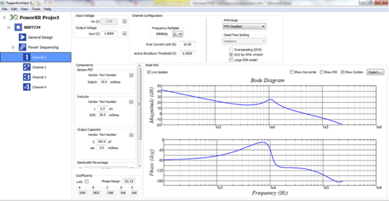
Figure 2shows the final interactive screen of the PowerArchitect with complete view of each channel’s parameters. All parameters may be altered by the user to accommodate the design criteria
Click image to enlarge
Figure 2. PA5.1 final screen showing all the selected and calculated parameters
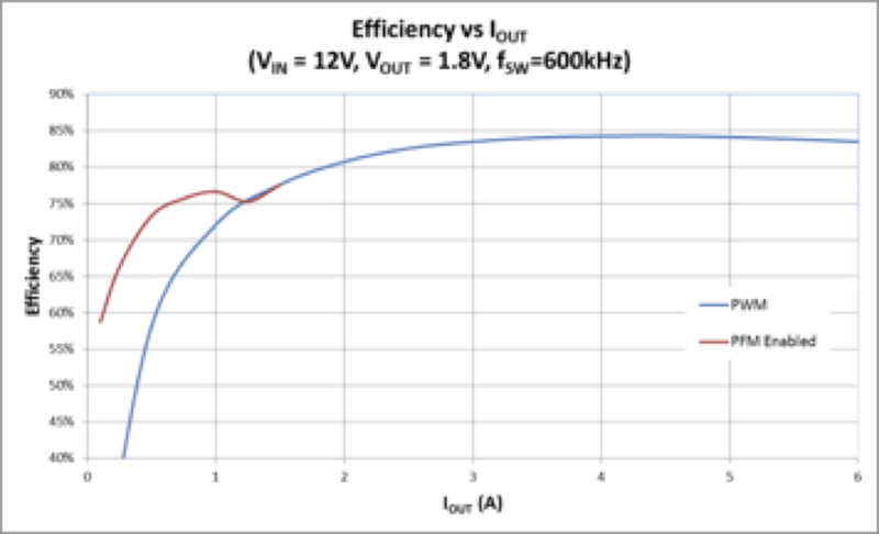
Figure 3shows the efficiency for a 12V to 1.8V step down conversion. Figure 4 shows the thermal images of the module running at full power for the 12V to 1.8V case. The maximum module temperature will ultimately depend on the power losses and the available PCB copper area(s) that act as a heatsink and help radiate the heat.
Click image to enlarge
Figure 3. Efficiency measurement, Vin=12V, Vout=1.8V at 600KHz switching frequency

Click image to enlarge
Figure 4. Infra-Red camera image, Vin=12V, Vout=1.8V at 600KHz switching frequency
Advanced Feature Set
• XRP9711 power management module offers the highest in-class power density in the industry with excellent package thermal resistance of both junction-to-case (θJC) and junction-to-ambient (θJA) in a 12mm x 12mm x 2.75mm Land Grid Array (LGA) package.
• Industrial applications demand very high reliability. This module offers this due to the fully optimized components with the proper design factor of safety criteria and the use of one component (the module) versus several.
• I2C and five GPIO ports for reporting and remote control functions by a host controller/CPU.
• Matching of the control IC and the power train components saves time sourcing, selecting and testing MOSFETs, inductors and capacitors etc.
• Saves time on PCB layout and potential re-spins to optimize efficiency, EMI and temperature rise of the application.
• No need to procure and stock multiple parts, one part does it all with improved reliability.
• Fully independent four channel multi-phase DPWM controllers.
• An internal 5V LDO that can be used by the design engineer for any housekeeping tasks up to 135mA.
The SMBus Compliant - I2C interface
Because of the complexity and high reliability requirements of industrial applications, System controllers are required to maintain an up-to-date health and performance status of its power converters. This can easily be done using the SMBus available on XRP9711. The module controllers continuously update the status of all four channels allowing measurements of per channel input and output voltages and output current. This allows the controller to gauge the system power demand at any time and implement fine-tuning on the fly adjustments to individual rails. This includes voltage margining i.e. incrementally ramping up or down the output voltage for optimum performance as in the case of CPU sleep mode.
There is also a measurement of device temperature feature. This is a valuable reading from the reliability and continuous operation point of view. The system controller can implement software routines to manage power consumption on an overall system basis by allowing consecutive sequencing of power demand when possible rather than simultaneous demand.
At times of low activities, standby and sleep modes may be implemented by enabling and/or disable individual rails or by voltage margining bringing the power consumption to a minimum and reducing the overall demand on the PoE system.
Other features
-Reporting of fault conditions: over voltage, over current and over temperature.
-On a dynamic basis, the system controller can adjust all fault limits as well as disabling/enabling faults.
-Read Power Good flag status.
-Soft-Start and Soft-Stop time control.
-Access to modify or read internal registers that control or monitor.
Conclusion
XRP9711 is a versatile power management module that offers significant advantages over other solutions on the market today. While the turn around cycle for new products from concept to product release is getting shorter, this line of products takes away the time, expense and worry of power management system design and implementation. This allows design engineers to concentrate on the innovative aspects of their new products and be free of concerns about the exacting performance specifications of their power management implementation.