A Push-Pull Topology for DC-DC Converter 12 V EV Applications
High frequency switching and energy storage components such as inductors and capacitors help produce very efficient circuits in DC-DC converters....
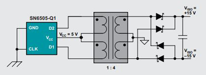
Figure 1. A push-pull converter helps to streamline an isolated power supply design in 12V EV applications.
DC-DC converters are employed in many high voltage applications such as ultra-capacitor energy banks, motor drives, high voltage battery systems and solar inverters. They’re one of the fundamental blocks of a power electronic design and are used to ‘condition’ voltage from one level to another – either to step-up or step-down voltage.
For increased safety reasons, push-pull DC-DC converters are becoming more and more common in electric vehicle (EV) applications where galvanic isolation is a requirement. Making them particularly attractive for automotive applications, they produce low EMI emissions, are highly efficient and have a small footprint. The push-pull configuration is ideal for battery management systems (BMS), on-board chargers and traction inverters that need to isolate high voltage circuits from low voltage circuits. Therefore, push-pull transformers are the solution of choice to isolate power in DC-DC converter systems.
There are many benefits of the push-pull topology, but efficiency and stable current top the list. Unlike typical flyback and forward topologies, the push-pull topology offers high efficiency at a stable input and output current. Plus, the push-pull has a lower ripple current, which contributes to higher efficiencies and consequently, a smaller footprint.
Push-Pull DC-DC Converter Background
Figure 1 shows a typical power supply application that would use a push-pull transformer. Because the input voltage in this power supply is limited to 5 V, the range of applications are also limited to ones that operate in the 12 V or 24 V range. The push-pull converter is a two-switch topology that has very high efficiency. It requires a transformer, so it transfers power from primary to secondary in each switching cycle.
DC-DC converters are a necessity in high voltage environments, such as for interface/bus isolation and isolation of digital circuits where 12 V is typically the voltage used. For example, a DC-DC converter with a 2:1 12 V power rail is commonly used in a communication interface system. Here, the DC-DC converter system would provide galvanic isolation between the signal isolation unit and the transceiver unit.
Electrical and Mechanical Advantages
Push-pull transformers offer many electrical and mechanical advantages. In addition to the high efficiencies with stable input and output current mentioned above, a push-pull design is used in open-loop configuration, so it requires no feedback, thus permitting a simpler end design. In addition, the transformer offers good core utilization as it draws current from both halves of the switching cycle.
The low EMI emissions due to the push-pull converter’s balanced configuration is a definite advantage to meet strict regulations on EMI in automotive applications. Transformers will inherently have parasitic capacitance between primary and secondary windings. This allows a path for the common mode currents to flow across the barrier, therefore, increasing the emissions to asymmetric switching converters. The push-pull’s balanced configuration will help to reduce the net flow of common mode currents as they will, in fact, cancel each other.
From a mechanical standpoint, push-pull transformers are typically available in a smaller footprint than flyback transformers. And, because push-pull transformers are designed as “pure” transformers, they usually have physically smaller ferrite cores compared to flyback transformers. Plus, there is no gap required in the ferrite core so the device’s effective permeability remains high and the magnetizing inductance can be quite high for a low number of turns.
Given a sufficiently high switching frequency and low DC voltages of a push-pull transformer, the flux generated (Volt Seconds per Turn) remains well below the saturation point. Contrast this to the split ferrite core in a flyback transformer where more turns are needed to ensure the current does not saturate the transformer. If there are tight space considerations and restrictions, the DC resistance will inevitably increase with the higher number of turns, resulting in reduced efficiency.
Specifying a push-pull transformer with a toroidal core is highly advised as there is no need for a gap, and a toroidal core is known for providing good coupling between windings. This is because the flux has a short distance to travel and there is little dispersion between windings. The relatively high inductance factor of a push-pull transformer with a toroidal core means it is possible to achieve high magnetizing inductances without a high number of turns.
Importantly, a toroid core can be enclosed in a housing separating the core from the circuit board. This difference automatically minimizes the footprint on a PCB in a 12 V EV application where creepage and clearance safety distances are required as defined by the standards for insulation (IEC 60664) and communications equipment (IEC 62368) that mandate a specified distance between the high voltage hazardous side of the PCB and the low voltage side. Conversely, if the core is exposed, the clearance would be significantly reduced and would need to be compensated by additional space of the plastic carrier.
Designing for Maximum Creepage/Clearance
A new generation of push-pull transformers are being designed that make full use of the enclosure around the ferrite core to maximize creepage and minimize the footprint. In these designs, the core is not visible from the pins, which allows the clearance pin to core to be measured up the wall of the device and down the joint between the lid and the side wall. The effective tracking distance over the insulated wire from pin to core is maximized by running the insulated wire around the outside of the component.
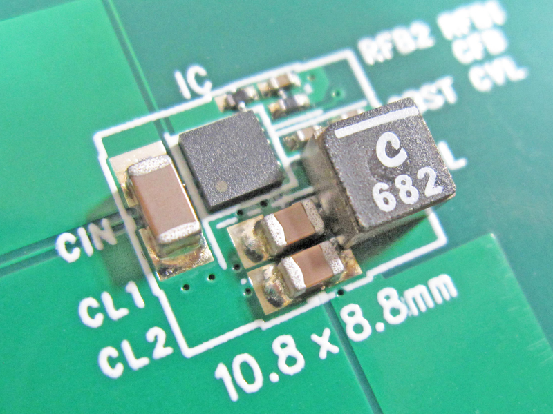
Bourns has taken this design approach that features a press fit of the lid against the side wall and the wraparound insulated wire with its Model HCTSM8 series transformers. These push-pull transformers can obtain a creepage and clearance of 8.0 mm despite having a nominal height of just 6.5 mm and a distance from pad to pad on the PCB of 11 mm max.

Click image to enlarge
Figure 2. Bourns Model HCTSM8 features an 8.0 mm creepage and clearance distance and consulting table F.4 of IEC 60664, this transformer offers a working voltage of 800 Vrms. Inverters and battery packs with rms voltages of up to 800 Vrms requiring reinforced insulation could use the HCTSM8 for isolated DC voltages for a gate driver for an IGBT or SiC MOSFET or to isolate DC power for a microcontroller or voltage monitoring IC or transceiver.
Putting Push-Pull Transformers to Work
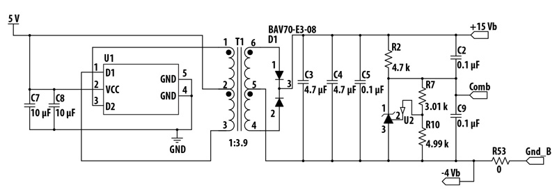
To generate plus and minus voltages for a gate driver, a circuit configuration using the Bourns Model HCTSM8 is provided as an example. The device in this example is driven by an integrated Texas Instruments SN6501 push-pull driver. The Texas Instruments device operates at a high frequency (400 kHz) and has a fixed duty cycle of 50 percent.
The output relationship in a push-pull driver with Input Vin and Output Vout and duty cycle D is as follows: Vout = 2 x D x n x Vin where n is the turns ratio from secondary to primary. Model HCTSM8 has 11 different standard turns ratios.
Because the Texas Instruments SN6501 device uses internal MOSFETs whose maximum voltage rating is 5 V, the Vin cannot exceed this level. And in order to generate 12 V, which is required to switch on an IGBT, it requires a turns ratio of 2.5.
It is not possible to push D beyond 50 percent in a push-pull transformer as the time to magnetize and demagnetize the core must be balanced or saturation will occur. The negative voltage can also be generated from the same transformer by attaching a shunt reference between the ground rail and a negative output. The push-pull transformer provides the 15 V needed for an isolated gate driver IC. The optimum operating point for this application is between 100 mA and 150 mA output current.
Click image to enlarge
Figure 3: A typical circuit generating diagram showing plus and minus voltages.
Transformers for Efficient Isolation
As the range of applications for high voltage driven equipment in transportation and other markets increases, so too will the demand for stable, high quality and standardized isolated power designs in applications such as modules in high voltage battery or ultra-capacitor packs. Next-generation push-pull transformers give EV designers the right combination of isolated power with low voltages.
The examples provided highlight that the combination of the Bourns Model HCTSM8 series transformers along with the TI SN6501 drivers are ideal solutions to isolate a 12 V bus rail in a communications system, or a power supply for the switching of IGBTs. Bourns HCT transformers are qualified to be used with Texas Instruments’ SN6501 and SN6505 transformer drivers, which have a maximum operating voltage of 5 V for isolated power supplies.