A Quick Guide to Automotive DC-DC Converter Test
Strategies in DC-DC converter development include reduction in size and higher efficiency in order to provide advantages to their customers
An automotive DC-DC converter receives high-voltage battery output and converts it to a lower voltage to power on board devices such as the instrumentation panel, entertainment system, sensors, LED lighting, and any other on board devices requiring low voltage DC power. Manufacture’s strategies in DC-DC converter development include reduction in size and higher efficiency in order to provide advantages to their customers. This development leads to more rigorous testing. Chroma’s expertise in power conversion test equipment, software and fixtures provide accurate and comprehensive testing of automotive power components including DC-DC converters.
This article provides test descriptions as well as the equipment required to confirm that the DC-DC converters are operating within their specified limits. These tests can be used for design verification, production, incoming inspection, or qualification testing.These tests can be run manually with standalone equipment or can be automated by integrating equipment into an automated test system (ATS) with dedicated software.
Input Turn-On, Input Turn-Off Voltage and Timing Tests
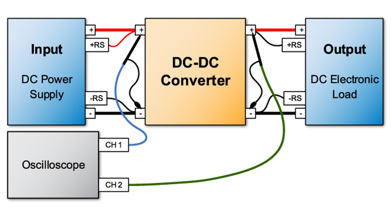
DC-DC converters have a specified input voltage operating range. To confirm the DC-DC converter works properly at the entire range of input voltages, they are tested using a programmable DC power source to provide the input voltage and power. A DC electronic load is used on the output of the DC-DC converter to simulate the device that would be powered from the DC-DC converter.
To test the minimum input voltage turn-on level, the DC-DC converter is turned on using the nominal input voltage and applying the maximum rated output current using the electronic load. The input voltage is then decreased until the units output begins to drop or the minimum input voltage setting is met.
To confirm that the DC-DC converter would turn on with a Maximum Load on the output, the input voltage would be set to the minimum and toggled off and on while measuring the output voltage and current. The output voltage, ripple, and noise are measured to see if the lower input voltage setting has any effect on the output stability or ripple.
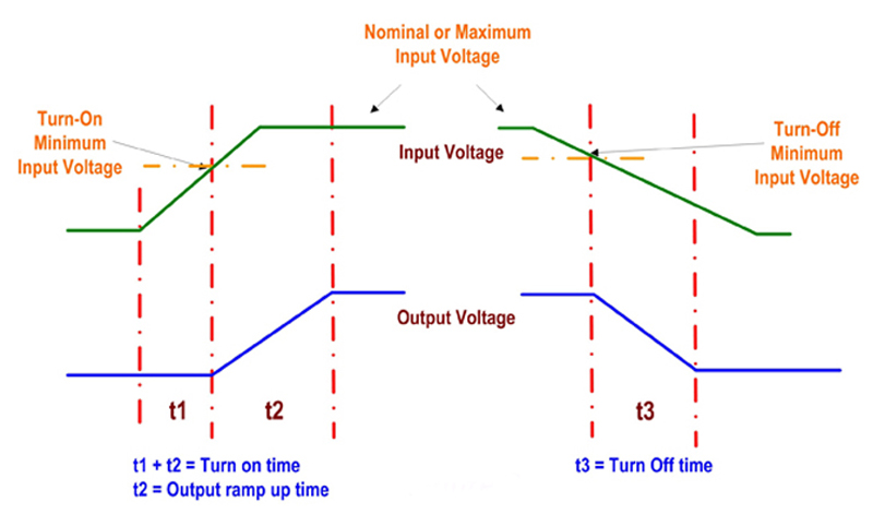
This setup also tests and measures the Turn-On time and Turn-Off time and Hold-Up Time (See Figure 2 & 3). An oscilloscope is used for the ripple and PARD measurements. The Chroma 63600 DC Load can display and measure waveforms for the applied voltage and current in as low as 2uSec sample rate using the Digitizing Measurement feature.
Turn-On time indicates the timing from the point the minimum input voltage is reached to the time the output voltage is within the output regulation limits. Turn-Off time indicates when the input voltage drops below the specified minimum and the output turns off or drops to zero volts (See figure 2).
Click image to enlarge
Figure 2: Turn-On & Turn-Off Time
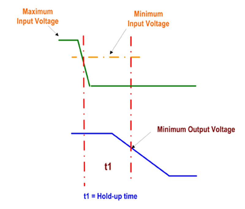
The Hold-Up test indicates the timing from when the input drops below the minimum input voltage and the output voltage drops below its minimum regulated output tolerance (See figure 3). This also indicates how well the output of the DC-DC converter handles short interrupts and drops in the input voltage. If the DC-DC converter has an Input Fault Detection Signal, this can be used to trigger the test. Chroma’s 63600 DC Load can use that trigger to capture and measure the Hold-Up timing without the need for an oscilloscope.
Click image to enlarge
Figure 3: Hold-Up Time
Output Line Regulation
This test confirms that the output voltage stays within specified regulation limits when the input voltage is varied from minimum to maximum operating voltage. During this test, output voltage is monitored and the total voltage deviation is recorded while varying the input voltage from minimum to maximum limits. The block diagram in figure 1shows the typical test set up.
If the measurement accuracy of the output load and input DC source are adequate, then no external measurements device is needed. The Chroma 63600 Loads and 62000P DC Power Supplies have accurate measurements for voltage, current and power, thus, requiring no external DMM.
Output Load Regulation:
To insure the DC-DC converter output voltage stays within the specified regulation tolerance, the load is varied from minimum to maximum current per specification and the absolute delta voltage is calculated. Using the delta voltage, the percentage of deviation is calculated and compared to the specified load regulation limits.
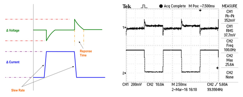
Output Transient Response Deviation and Time
This test determines how the output voltage responds to a sudden change in current. The measurement includes the maximum output voltage deviation and the time it takes for the voltage to recover to its regulated output nominal voltage tolerance. Figure 4shows the pulsed current and voltage deviation. The DC load is set for a minimum and maximum current and then set for the slew rate for the rising and falling edge of the current transition. The frequency and duty cycle can also be set for the pulsed current. Chroma 63600 and 63200A loads can be programmed for all the settings required for a dynamic load and up to 50 KHz frequency with a duty cycle programmable from 1 to 99%.
Click image to enlarge
Figure 4: Pulsed Current and Voltage Deviation
Output Ripple & Noise Voltage
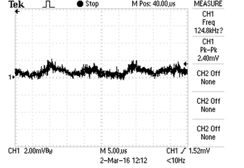
The output ripple and noise or periodic and random deviation (PARD) reflects the output voltage of the DC-DC converter and its ability to filter out ripple and noise. Various topologies used in DC-DC converters have different internal switching frequencies which are reflected in the output ripple frequency. Higher frequency noise can be generated from the internal chopper circuit transients. Output noise and ripple can be measured using an oscilloscope, however, the Chroma 63600 DC electronic load can display the output ripple using its digitizing measurement function. Figure 5 shows a scope screen shot of a DC-DC converter output ripple voltage.
To avoid erroneous noise it is important to minimize the length of the ground wire on the voltage probe.
Click image to enlarge
Figure 5: A Scope Screen Shot of a DC-DC Converter Output Ripple Voltage
Output Over-Current Protection
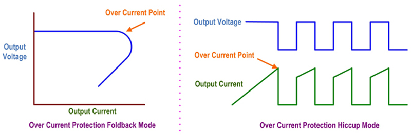
The output of the DC-DC converter Over-Current Protection is intended to protect the DC-DC converter and the device that it is driving when the load exceeds the maximum rated current of the DC-DC converter. There are different methods used in over current protection but typically they are FOLD BACK current limit and pulsing current limit also referred to as HICCUP current limit.
The differences between the 2 methods are:
FOLD BACK Current Limit: as the load current increases above the current limit set point, the output voltage begins to decrease and limits the output current supplied to the load.
HICCUP Current limit: turns the output off when the output current exceeds the rated current limit point and then turns the output back on. If the load continues to be over the current limit set point then the output will keep turning on and off hence the name hiccup. (See figure 6)
Click image to enlarge
Figure 6: Over Current Protection Fold Back Mode versus Over Current Protection Hiccup Mode
Output Over-Voltage protection:
Most DC-DC converters have a built in protection circuit, referred to as Over Voltage Protection (OVP), that will shut off the output of the device when the output voltage is detected to be over the maximum voltage limit. This is to protect the DC-DC converter from external excessive voltage applied to its output. If the DC-DC converter has an adjustable output, trimmed or programmable output voltage, it may be possible to increase the output voltage until the OVP point is exceeded and the protection circuit is activated. If it does not have an adjustable output then an external voltage source can be applied across the output terminal, increased to the OVP trip point, and then removed to see if the output has triggered and turned off. If the DC-DC converter has an OVP Fault signal, this can be used to determine if the output detected the OVP and shut off the output. The output voltage is monitored to determine when the OVP occurred and then compared to the OVP specified limits.
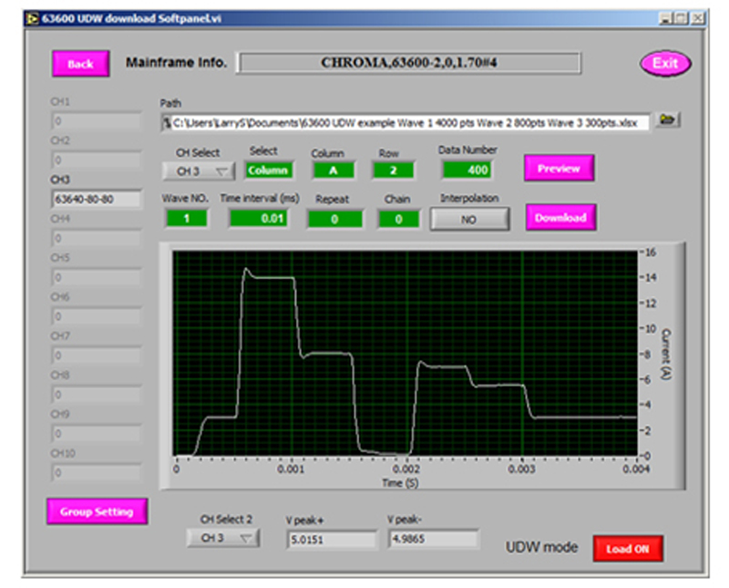
Custom Load Waveform Simulation or Real World Load Simulation
Some DC-DC converters have specific applications where the load may have unusual dynamic changes and waveforms. Using an electronic load that can replicate actual load waveforms to test the DC-DC converter under real world conditions is needed. Chroma’s DC Electronic Loads come equipped with User Defined Waveforms (UDW) up to 50 KHz frequencies and slew rates of 10A/usec. Waveforms can be stored in the loads memory and recalled manually or remotely. Figure 7shows a Screen shot of the Chroma software that allows for loading and replicating current waveforms on the 63600 load and high power 63200A DC loads.
Click image to enlarge
Figure 7: Screen Shot of Chroma Software
Efficiency Test
Efficiency determines the internal power dissipated by the DC-DC converter and how efficiently it transfers the input power to the output of the converter. This test is usually conducted at the nominal input voltage and with the output load set to nominal or maximum specified ratings. Both input and output voltage, current and power is measured and, using the formula below, the Efficiency Percentage is determined. Then it is compared to the DC-DC converter specification for efficiency to determine if it is in specified limits. This test can also capture the efficiency at various power levels and the data can be plotted to show the efficiency versus output current curve. Data can either be collected from a multi-channel power meter or from the input power source and output load.

Click image to enlarge
Output Trim Settings
For DC-DC converters that have adjustable outputs or Trim Settings, adjustments can be made manually or automated by using a Programmable Potentiometer or Programmable Resistor Array. The test is performed to verify the output adjustment range. All the previous tests mentioned can be performed to verify the DC-DC converter operates properly at different trim voltages.
Safety Test: Dielectric Voltage Withstand ACWV/DCWV (Hipot)
If the DC-DC converter has an isolation stage between the input and output, then functional insulation testing is required. Typically if the input voltage exceeds 60Vdc, the DC-DC converter may need to pass a basic insulation test. Also, if the device has a connection to safety earth ground, then a withstand voltage test or hipot test will need to be performed. The specific withstand voltage test is specified by the associated standard.
Chroma Systems Solutions
 Single.jpeg)