A Quicker, More Efficient Way to Market for BLDC Designs: Part 1 of 4

BridgeSwitch Application
Electric motors are currently the largest consumers of electricity in the world by a large margin. The Energy Research Centre of the Netherlands (ECN) estimates that 45% of all electricity generated globally is consumed by electric motors. Therefore, as part of the push towards higher efficiency, legislation is being introduced to raise the required efficiency of motors. In July 2021 the EU implemented its “Regulation on electric motors and variable speed drivers (EU) 2019/1781” to add a minimum efficiency limit on some motors that were previously excluded from the standard, and reduce the time allowed for other types of motors to come into line with efficiency requirements. The trend shown by such regulations is obvious – the minimum allowed efficiency will keep increasing over time. New motor designs should be made as efficient as possible to negate the risk of legislated replacement before their operational lifetime is over.
A wide variety of motors are covered by these laws, from the large motors found in infrastructure pumps to the tiny motors that power PC fans. Size is not the only consideration – the type of motor also matters. Previously, Brushed DC motors were widely used, but they were relatively inefficient with limited reliability – the brushes would wear down over time and require replacement. The need for higher efficiency and increased reliability over a wide variety of operating speeds and loads has resulted in Brushless DC (BLDC) motors becoming widely adopted for new designs.
BLDC motors eliminate the need for the physical contact between the brush and commutator. This one step eliminates the mechanical losses caused by friction and makes BLDC motors more suitable for long-term deployment. Since the rotor does not need to be powered, brushes and slip rings are eliminated, along with the commutator assembly simplifying construction. This also allows BLDC motors to output more torque per watt than a Brushed DC motor in a much smaller package.
BLDC motors use a permanent magnet as a rotor, which interacts with the electromagnetic fields generated by the stator coils. These coils are turned on and off in a precise pattern to ensure the rotor turns efficiently. This pattern is determined by a microcontroller (MCU) algorithm and uses sensors embedded in the motor to provide real-time feedback for accurate control. The microcontroller sends signals to switches controlling the current through the coils. Although MCU control adds some increased complexity to the motor driver, it provides a greater degree of flexibility and precision.
As the legislation concerning motor efficiency targets the operation of the whole motor assembly, each stage must be made to operate optimally to minimize overall losses. This includes the inverter used to supply power to the motor. The inverter’s performance is limited by heat. In addition to reducing the operational life of the inverter, poor thermal performance stops the inverter from delivering sufficient current to the motor drive when the driver is overheated. The typical solution to thermal problems is to use a heat sink, or an auxiliary fan in some cases. Neither solution is ideal. Both are bulky, which negates the advantage of having a smaller motor and both lead to higher BOM count, increased design complexity, and a less mechanically robust design.
Power Integrations(PI) – with extensive experience in developing highly integrated, high-voltage ICs for offline power conversion and gate driving – tackles this problem from two different directions. The first is to provide an efficient architecture that minimizes the heat dissipated. The second is to separate the phase drivers into individual ICs to provide a scalable solution that is flexible enough to support single-phase and multi-phase motors. The small amount of heat generated from losses in each driver is spread across the PCB, rather than concentrated in a single hotspot.
The result is the BridgeSwitch™family of Integrated Half-Bridge (IHB) motor drivers suitable to drive synchronous motors (BLDC or Permanent Magnet Synchronous Motors (PMSM)), as well as asynchronous motors (e.g., AC induction). BridgeSwitch devices can be up to 98.5% efficient and are intended for inverter designs ranging from 30 W (typical IRMS = 0.2 A) to 400 W (typical IRMS = 1.1 A). BridgeSwitch ICs incorporate the low- and high-side drivers, a controller, a level shifter and two N-channel 600 V fast-recovery epitaxial-diode FETs (FREDFETs) with integrated lossless current sensing. FREDFETs have extremely fast recovery body diodes, making them ideal for driving inductive loads. They offer a significant reduction in switching losses, as well as a soft-recovery characteristic to reduce EMI.
BridgeSwitch ICs are self-powered, which allows the use of a simpler system power supply, such as PI’s LinkSwitch™-TN2, to drive the microcontroller. A small non-isolated driver can be used, rather than the multi-output isolated flyback seen in conventional designs, further reducing the BOM, design complexity and board space. Built-in inverter diagnostics reduce the number of sensors required and the MCU processing overhead. BridgeSwitch ICs incorporate many hardware-based fault protection and external system-level monitoring functions. This hardware implementation not only provides a faster response than software protection, but also makes it much easier to gain UL/IEC 60730 approval due to the architecture’s hard-wired, cycle-by-cycle, low- and high-side overcurrent protection and onboard monitoring. The hardware implementation of these features means software requirements to meet UL/IEC 60730 are reduced from Class B to Class A, eliminating the need to recertify after software updates.
To allow designs to get to market even more quickly, PI has also developed several BLDC reference design kits (RDKs) for the BridgeSwitch family. The new reference designs provide up to 400 W output power without requiring a heatsink, and support applications with higher RMS currents in thermally challenging environments, such as compressors, range hoods, and residential and commercial fans and pumps.
See figures 1-5 ; None of these boards require a heatsink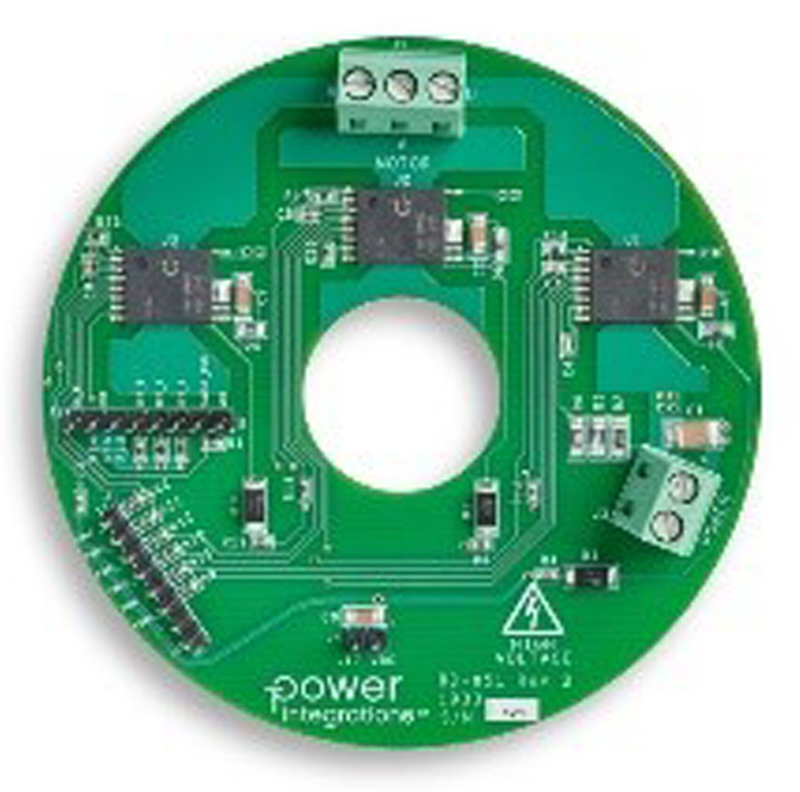
Click image to enlarge
Figure 1: RDK-851 is a 50 W high-voltage BLDC motor control design for fan applications using BridgeSwitch IC BRD1260C. This three-phase inverter with control input interface offers >93% efficiency. The design is available on an 88 mm diameter PCB
Click image to enlarge
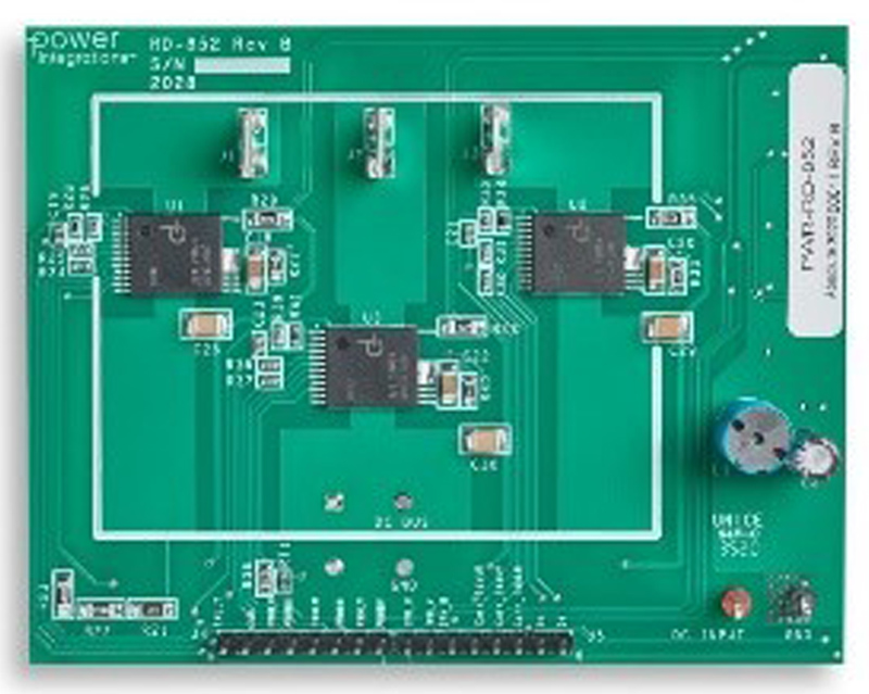
Figure 2: RDK-852 is a three-phase BLDC motor driver for pump applications up to 200 W. The design comes on a 65 mm x 50 mm PCB and uses BridgeSwitch IC BRD1263C in sensorless field-oriented control (FOC) operation. This 97% efficient solution employs a LinkSwitch-TN2 IC (LNK3204D) to supply the current sense amplifier and optionally provide external bias for the BridgeSwitch device
Click image to enlarge
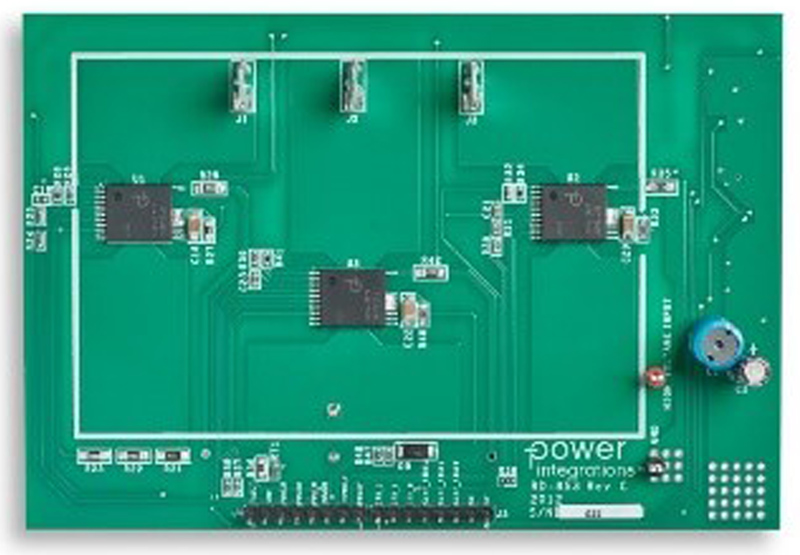
Figure 3: Rounding out the three-phase solutions is the 300 W RDK-853 compressor design that is over 98% efficient across the load range and is situated on a 95 mm x 75 mm PCB. This solution uses BridgeSwitch IC BRD1265C and LinkSwitch-TN2 LNK3204D ICs, and it supports any MCU for sensorless FOC through the signal interface with instantaneous phase current output signal and fault reporting for each BridgeSwitch device
Click image to enlarge
Figure 4: Rounding out the three-phase solutions is the 300 W RDK-853 compressor design that is over 98% efficient across the load range and is situated on a 95 mm x 75 mm PCB. This solution uses BridgeSwitch IC BRD1265C and LinkSwitch-TN2 LNK3204D ICs, and it supports any MCU for sensorless FOC through the signal interface with instantaneous phase current output signal and fault reporting for each BridgeSwitch device
Click image to enlarge
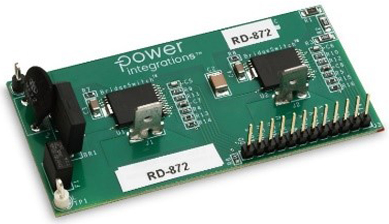
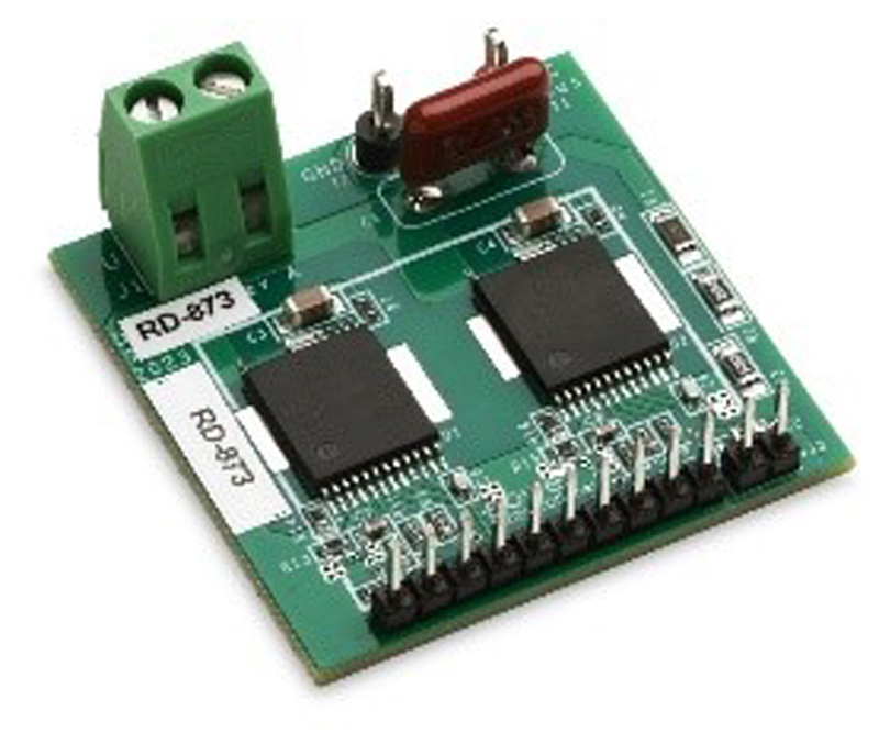
Figure 5: RDK-873 is a 30 W, 95% efficient compact BLDC motor driver. The inverter stage is implemented using two BridgeSwitch BRD1260C motor driver ICs in a full-bridge inverter configuration
To further simplify the design process, PI introduced Motor-Expert™, a motor control configuration and diagnostics application which provides a graphical user interface for all parameters and commands, as well as a terminal emulator for interacting with the motor controller in serial mode. A Motion Scope feature provides linear graphs of important controller variables viewable in real time.
For more information, please visit the Power Integrations website: power.com