Measurement and Evaluation of AC Losses
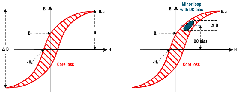
Figure 1. Typical B-H curve from positive saturation to negative saturation. When H is zero there exists Br which requires -Hc to return to zero. The area within the loop is core loss per cycle
What are AC Losses and why are they important? This paper discusses the physical effects and which issues must be observed by design engineers. Furthermore, an approach to determine AC losses with unmatched accuracy is being introduced.
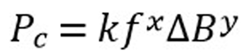
In 1892 Charles P. Steinmetz, working for General Electric presented his now classic paper “On the Law of Hysteresis” which contained his formula for hysteresis loss, today commonly referred to as the General Steinmetz Equation (GSE):
Click image to enlarge
Here we see AC core loss increases exponentially with both frequency (f) and flux density (B).
Knowledge of losses is important because the size of inductors and transformers is constrained by their ability to dissipate the heat generated by the losses. The smaller the device, the smaller its surface area and the lower the losses must be. Today’s world of miniaturization comes with many thermal challenges for all components.
What are losses?
When we speak of losses, there are two types, DC and AC. These types refer to the type of currents involved, whether it is steady state (direct current) or alternating current. Switch mode power supplies have both types. We sometimes simplify things to the equivalent heating current (Irms) which is the geometric sum of IDC and IAC currents.

Click image to enlarge
DC losses are straight forward, PDC = RDC * I2. AC losses are much more complex because the currents do not distribute evenly (skin and proximity effect) and depend on material properties like permeability and permittivity plus frequency, wave shape and phase shift.
What are core losses?
The root of hysteresis core losses is domain wall movement. When a soft magnetic material is influenced by an external magnetic field (current in a coil or nearby permanent magnet) the domains which we imagine to be like tiny magnetics within the material align themselves with the field. This takes energy and time. When the direction of current changes the domains reverse direction. When the outside influence is removed, the domains will spring back, but not completely. The energy in the spring back is returned to the system but the rest is expended as work done against the friction of other domains and is converted to heat. Higher frequency means shifting the domains more often requiring more energy, exponentially more. Domain movement is also proportional to flux swing. Greater flux swing equals more movement equals more energy required, not all of which is returned. The area within the BH curve represents the energy loss through one cycle (Figure 1).
Eddy current losses stem from the fact that the core itself is a turn like a winding. Generally, its resistivity is higher than the winding conductor and in the case of ferrite, considerably more. Eddy currents are therefore influenced by the resistivity of the core material, changes resulting from temperature, and the applied voltages on the windings. The higher the voltage, the greater the induced voltage regardless of duration (pulse width) and the higher the loss (Figure 2).
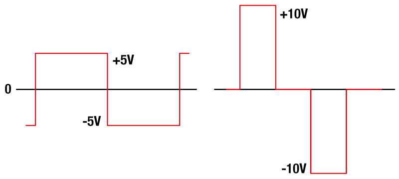
Click image to enlarge
Figure 2. Two waveforms with equal volt-seconds but the right waveform has twice the average losses of the left waveform. Calculated from P = V2*DC/R where DC = duty cycle, R = (core) resistance
The third contributor to AC loss is DC bias. At first this seems unintuitive because a static current does not cause any domain wall movement besides the initial change. However, when an AC waveform is DC biased (as ripple on a DC voltage), the minor hysteresis curve shifts to a different position along the full BH curve. Depending on the position, this can change its shape, hence the area enclosed by the loop, usually resulting in higher hysteresis losses. This can result in an unanticipated hot inductor. Traditional methods for calculating AC core loss do not account for this, adding further to its surprise appearance.
What is winding loss?
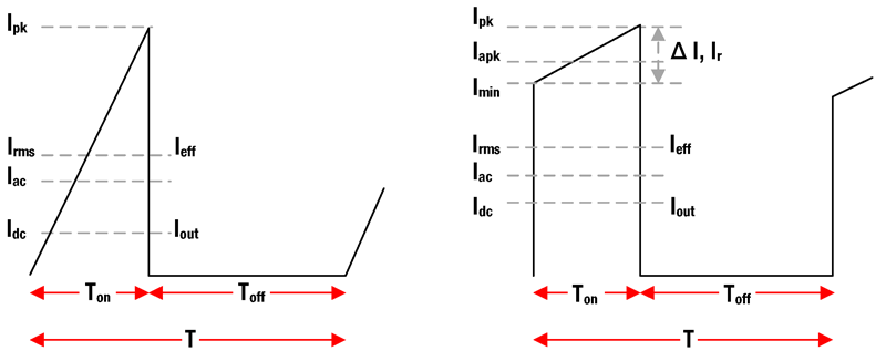
DC winding loss comes from the DC resistance of the conductor used for the winding. This is simply the measured DC resistance multiplied by the DC current portion of the current waveform squared, P = I2*R. The AC winding loss consists of skin and predominantly proximity losses from the AC portion of the current waveform (Figure 3).
Click image to enlarge
Figure 3. A waveform can be reduced to its dc and ac components, which are different depending on wave shape. Geometrically summed they are the rms value. Peak and ripple are only momentarily values
Skin effect is the result of high frequency currents only penetrating a small distance into a conductor, therefore not using the full cross-sectional area of the conductor and effectively increasing the resistance. Skin effect as commonly defined is only valid for a single conductor in free space far from other conductors. This is not the case in inductors or transformers where there are usually many turns, and layers of wire tightly wound together.
Proximity effect describes the influence of adjacent magnetic fields on the currents in a conductor. There are two effects. Adjacent wires with currents flowing in the same direction will attract each other (the fields between cancel) leaving the facing surface areas with little current. Adjacent wires with opposing currents will repel each other (fields add) and the facing surfaces will have a greater concentration of current with the opposite sides having considerably less.
What about temperature?
Inductors use various core materials including pressed powdered metals, fired ceramic ferrites, laminations and amorphous ribbons. Each material exhibits different variation over temperature. The properties of permeability, saturation, resistivity, and core losses are of primary interest. As frequency increases permittivity becomes important as well as the size of the core. At high frequencies cores exhibit a skin effect where the flux does not penetrate the core evenly.
How to measure AC losses?
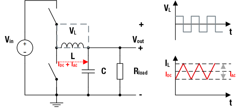
Würth Elektronikuses the MADMIX system from MinDCet NV. This is essentially a highly programmable and highly instrumented buck converter designed to reproduce real world working conditions for inductors and measure how they perform. The system operates over frequencies from 10 kHz to 10 MHz, duty cycles from 5 to 95%, voltages from 0.5 to 70 V, load currents up to 48 A and can make measurements over a wide temperature range of -45 to 225°C. Fully calibrated and verified by calorimetric measurements, it is the most accurate equipment available for measuring inductor performance. Because of its extreme versatility and programmability, inductors can be characterized over a wide range of operating conditions yielding comprehensive data sets. When setup to emulate continuous conductor mode, the effects of DC bias are automatically included. Power is measured going into and coming out of the test platform converter. Adjustments for ringing and switching losses are made in the software. Prior to loss measurement, the DC resistance is measured and later the DC losses are separated from the total losses (Figure 4).
Click image to enlarge
Figure 4. Schematic of DC-DC converter for loss determination and resulting waveforms
Deriving the losses
Ideally all the energy going into an inductor comes back out, but reality is different because of losses. The main losses are from the DC resistance of the windings, the AC losses of the winding and the AC core losses. If the input and output power can be accurately measured, the difference is the total loss. This is easily done by integrating over the voltage and current waveforms for duration of a period (one cycle).

Click image to enlarge
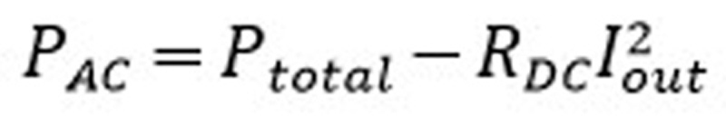
From this can be subtracted the DC losses since the DC output current and dc resistance of the coil are easily measured. The remainder is the total AC losses, which are more difficult to separate into individual components.
Click image to enlarge
The core losses can be determined from the B-H curves allowing separation of winding losses, but it is not possible to separate skin and proximity effects losses. Furthermore, it is not necessary from a user perspective because the main concern is to know how hot the inductor will get from the total losses under its operating conditions. This depends on the size of the part and how it is mounted with regard to cooling.
This is the purpose of knowing the total losses of an inductor. The losses are dissipated as heat that must be removed by conduction to the pcb and by convection to the air. Each inductor in REDEXPERT has a ‘Rated current’ based on the DC current that causes a 40°C temperature rise when mounted on a standardized pcb and operated in still air. This means the total losses (AC + DC) must be less than the loss generated by the inductor’s rated current (RDC * Irated2) provided you have an equivalent copper surface area to that of the test board. REDEXPERT gives the temperature rise of an inductor based on different ambient temperatures and DC currents, but you still must make the transition to your application based on the total losses and your specific layout.
Würth ElektronikeiSos has reduced this empirical data to equations where the ac losses are more than a function of the frequency and flux density as in the Steinmetz model. The WE model separates the losses into the DC losses and the total AC losses. No attempt is made to separate the AC core losses from the AC winding losses. In the end, they both contribute to the losses, which cause temperature rise.
REDEXPERT
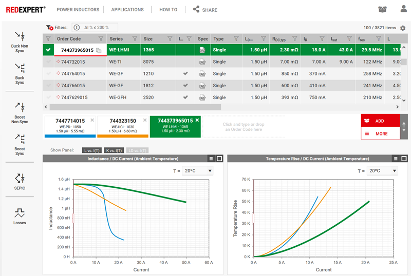
Over the years Würth ElektronikeiSos has taken thousands and thousands of measurements of inductors in its portfolio. This rich set of data has been reduced to equations that give the AC losses for the inductors based on the operating frequency, duty cycle, DC bias, ripple current, etc. It is important to realize this is not a design formula because the measurements used to generate the formulae are all component specific considering the construction methods and materials. This is why it is so precise. The Würth ElektronikeiSos online selection tool, REDEXPERT (Figure 5) provides a very convenient way to access this information and compare multiple inductors instantly.
Click image to enlarge
Figure 5. Tables and charts in REDEXPERT allow quick and accurate comparison of inductors
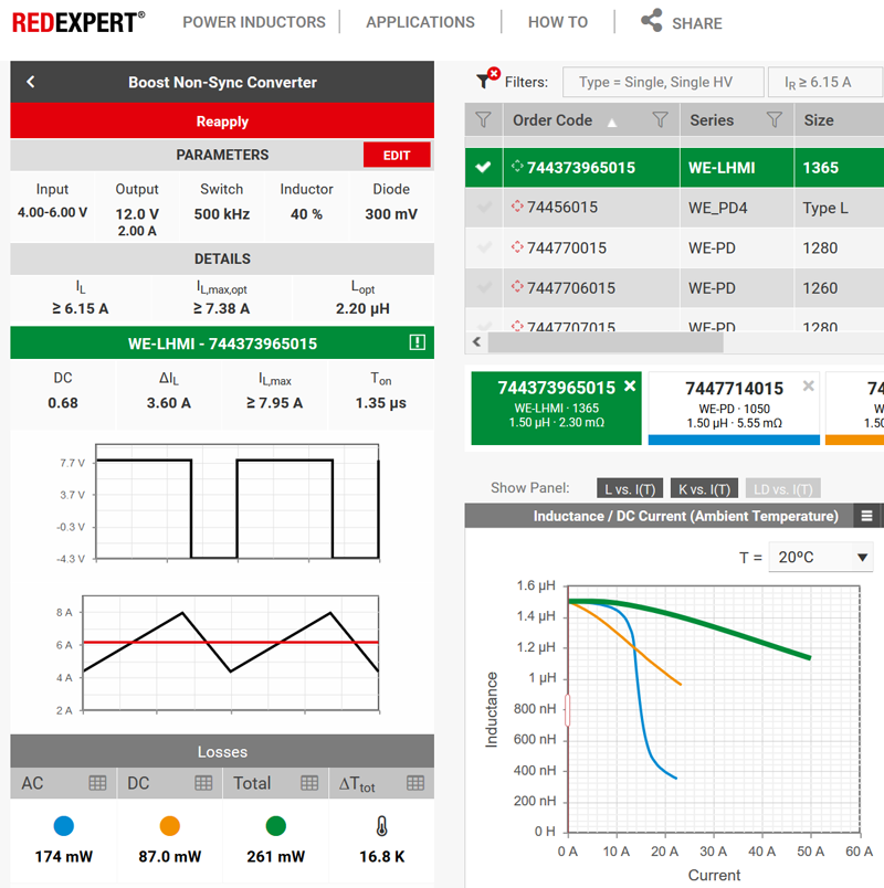
A nice feature of REDEXPERT is that it will save your work automatically. Simply click on the share icon in the top menu bar and a unique URL will be presented. Save it to your design book, email it to yourself or to a colleague to share and the exact display you see will be reproduced when you need it (Figure 6).
Click image to enlarge
Figure 6. Detailed information on losses and temperature rise are only a click away. (URL https://we-online.com/re/5gYnYCqG)
References
[1] Brander, T., Gerfer, A., Rail, B., Zenkner, H.,Trilogy of Magnetics, 2018
[2] Bramanpalli, R., ANP029 Accurate Inductor Loss Determination Using WürthElektronik’s REDEXPERT,
[3] De Smedt, V., MADMIX Inductor Models, MinDCet,2017