AC Losses in Magnetic Components
Be cautious of hot inductors!
In power supplies, storage inductors play an important role. Unexpected overheating of the magnetic component in the inductors used should be avoided at all costs. The AC losses that are often responsible for this are difficult to estimate. The online simulation tool RedExpert facilitates the development work considerably.
Despite often looking like simple devices, designing a power supply is a complex project with many conflicting requirements pressed on by the end user and a multitude of regulatory agencies. The end user wants the least expensive solution, often in the smallest package with the highest reliability. The regulatory agencies want minimum thickness insulations and creepage distances, which result in larger components. The designer must possess broad knowledge in many areas besides electrical, mechanical and control theory. Add to this the mystery of magnetics where invisible forces act on materials to store or transform energy based on age-old cryptic formulas from the past, is it any wonder the designer seeks a simpler solution to select the proper magnetic device.
Take the buck regulator as an example simply because it is the most widely used topology for reducing voltage in non-isolated circuits. The quest to reduce size is realized by increasing the switching frequency. This allows passive components like inductors and capacitors to be smaller because the energy storage per cycle is lower. Their size is proportional to their energy storage capacity. However, reducing the size reduces the surface area available to dissipate heat from losses making thermal design more critical.
In magnetic devices, there are two sources of losses, the windings and the core. Both can be further divided into subtypes (Table 1).
What are core losses?
The root of hysteresis core losses lies in the movement of the magnetic dipoles and, at high saturation currents, in the displacement of the domain walls in the core material. When a soft magnetic material is influenced by an external magnetic field, caused by a current in a coil or a nearby magnetic field, the magnetic dipoles in the domains (tiny magnetic regions with elementary magnets in the material), align themselves with the field. This takes energy and time. When the outside influence is removed, the magnetic dipoles in the domains reorientate, domain walls jump back, but not completely. When the direction of current changes the magnetic poles in the domains reverse direction, but not completely. The energy in the spring back is returned to the system but the rest is expended as work done against the friction of other domains and is converted to heat. The higher the frequency, the more the elementary magnets in the domains and domain areas are moved and shifted per second and the more energy is required, exponentially more. The movement of the magnetic dipoles is also proportional to the flux change. Greater flux swing equals more movement equals more energy required, not all of which is recovered. The area within the BH curve represents the energy loss through one cycle.
Eddy current losses stem from the fact that when alternating currents flow through a conductor, a voltage is induced according to Faraday’s law in proportion to the rate of change of the magnetic field. The core itself is like a winding, and although the ferrite material used in high-frequency technology has a high resistivity, the small particles conduct. This resistivity characteristic changes exponentially downward as temperature increases. Faster rise times induce larger voltages. Pulses of higher voltage have exponentially greater losses according to P = (V2*D)/R (where D = duty cycle, R = resistance).
Depending on topology, a third contributor to AC loss is the effect of DC bias. At first this seems counter intuitive because a static current does not cause any movement of the magnetic dipoles in the domains beyond the initial change. However, when an AC waveform is DC biased (as a DC current offset of an alternating current), the minor hysteresis curve changes its shape as a function of the polarity and amplitude of the current at different positions along the BH curve (figure 1). Measurements show at low bias levels the influence is small, but at higher levels there is a significant increase in losses. It is understood, that as the magnetic material approaches saturation, when almost all magnetic dipoles are aligned, more energy is required to align the remaining magnetic dipoles of the domains. Traditional methods for calculating AC core loss do not account for this, adding further to an unexpected surprise.
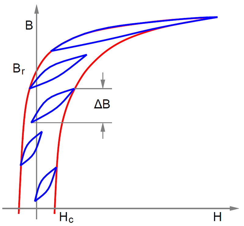
Click image to enlarge
Figure 1. Minor loops shown at various positions along the major loop. They all have the same peak-to-peak flux swing. The loop area is hysteresis core loss per cycle
Finally excess losses are attributed the difference between calculated losses and measured losses. These result from things such as relaxation effects, excess eddy currents, stray losses and other lesser understood phenomena.
What is winding loss?
DC winding loss comes from the DC resistance of the conductor used for the winding. This is simply the measured DC resistance multiplied by the DC current portion of the current waveform squared, P = I2*R. The AC winding loss consists of skin and predominantly proximity losses from the AC portion of the current waveform.
The skin effect is caused by the fact, that at high frequencies the current density is no longer constant across the conductor cross-section because the current is displaced towards the surface of the conductor due to finite inductances. The changing current in the conductor creates a magnetic field around the wire by Faraday’s law but which by Lenz’s law induces a current back into the conductor in the opposite direction. These eddy currents cause cancellation at the center and reinforce currents near the outer surface. (figure 2) Skin effect as commonly defined is only valid for a single conductor in free space far from other conductors. This is not the case in inductors or transformers where there are normally many turns and layers of wire tightly wound together.
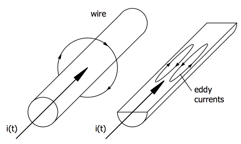
Click image to enlarge
Figure 2. Alternating currents induce a magnetic field, which introduces eddy currents in the opposite direction, cancelling current flow in the center region and reinforcing it in the outer region
Proximity effect describes the influence of adjacent magnetic fields on the currents in a conductor. There are two effects. Adjacent wires with currents flowing in the same direction will attract each other (the fields between cancel) leaving the facing surface areas with little current, figure 3 a. Adjacent wires with opposing currents will repel each other (fields between add together) and the facing surfaces will have a greater concentration of current with the opposite sides having considerably less. See figure 3 b.
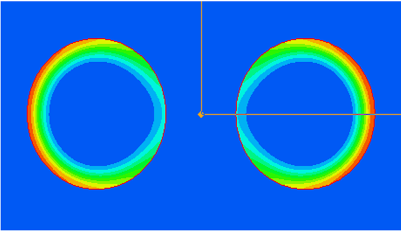
Click image to enlarge
Figure 3a. Currents in adjacent wires, with current in the same direction
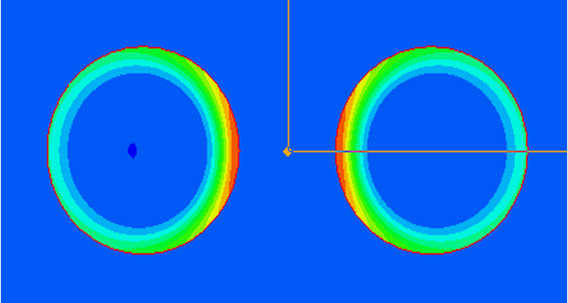
Click image to enlarge
Figure 3b. with current in the opposite direction. Red is high current density; blue is low density
In transformers, the current is in the same direction within a winding but the opposite direction between primary and secondary windings. Inductors with one winding have current only in the same direction. One of the most important influences in AC winding losses is the number of layers. This is especially prevalent with inductors because with each layer the MMF (Magneto Motive Force) increases and is not cancelled by a secondary winding. With each additional layer, the losses increase exponentially, since the magneto motive force is the product of the magnetic flux and the magnetic resistance (reluctance).
It’s clear to see why single layer, edge wound flat wire inductors (aka helical wound coils) have become so popular in high current inductors. The current, whether AC or DC will still crowd around the path of least resistance which is the inside diameter but the added proximity losses from multiple layers is gone.
Inductor selection with REDEXPERT
Over the years, Würth Elektronik eiSos has taken thousands of loss measurements of inductors in its portfolio under real use conditions – rectangular waveforms, duty cycle, DC bias, ripple current, and temperature. This rich data set of total AC losses includes all the effects of construction methods, wire types, core material and excitation waveform. No need to do tedious and complicated calculations, often with missing information or to try modelling losses with arrays of resistors, inductors, and capacitors in order to run simulations for each possible choice.
The Würth Elektronik eiSos online inductor selection tool, REDEXPERT (figure 4) provides convenient access to this data with the ability to compare multiple inductors instantly. Simply select the converter type, enter the basic operating conditions and all usable inductors are presented. From these, sort and select down to a list of inductors that meet your requirements, including size, height and shape. Easily adjust operating conditions to check the extremes of your design. Charts immediately give the full performance range including temperature effects. This allows you the user to compare the merits of each inductor to their own satisfaction. Then download only the most suitable inductor’s file, and at the same time you can order free samples.
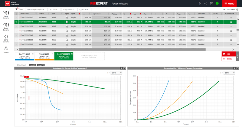
Click image to enlarge
Figure 4. Tables and charts in REDEXPERT allow quick and accurate comparison of inductors
REDEXPERT will save your work automatically by clicking on the share icon in the top menu bar where a unique URL will be presented. Save it to your design book, email it to yourself or a colleague to share. The exact display you see will be reproduced when you need it again.
References
[1] Baguley, C., Carsten, B. Madawala, ‘The Effect of DC Bias Conditions on Ferrite Core Losses’, IEEETransactions on Magnetics, Vol. 44, No. 2, February 2008
[2] Barbisio, E., Fiorillo, F., Ragusa, C., ‘Predicting Loss on Magnetic Steels Under Arbitrary Induction Waveform and With Minor Hysteresis Loops’, IEEE Transactions on Magnetics, Vol. 40, No. 4, July 2004
[3] Online simulation platform REDEXPERT: https://redexpert.we-online.com/


