How to incorporate new energy sources such as solar, wind turbines and batteries with DC outputs into buildings while maintaining efficiency
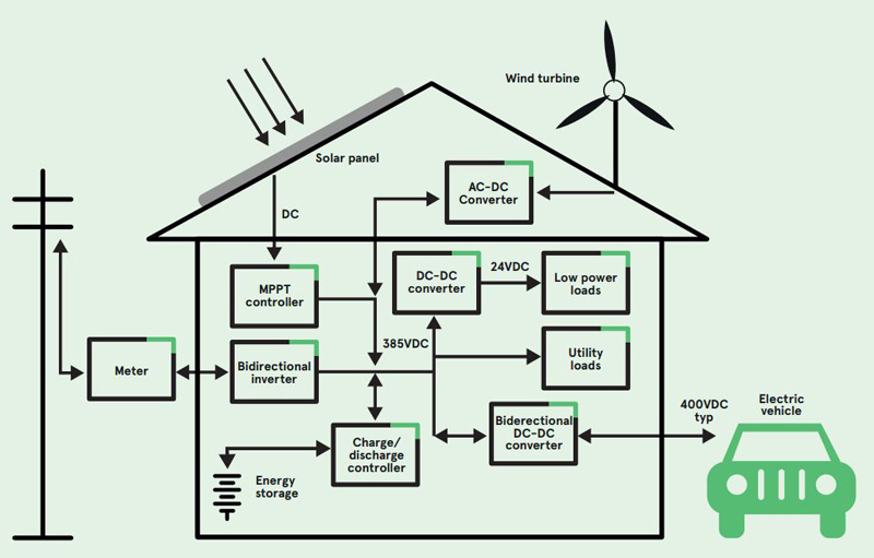
Figure 1: The DC-powered home
Most electronics requires DC at board level and even motor-driven AC machines are often ‘smart’, inverter-driven types, that operate internally from a high voltage DC bus. At the same time, buildings are becoming more ‘intelligent’ adding convenience, productivity and reducing energy consumption. This can only mean more DC-powered electronics, interconnected in the IoT, with widely distributed sensors, actuators, and controls.
Mini, micro, and nano grids are planned forsmart buildings in the future, coupled with local renewable energy sources, making transmission losses less of an issue. For continuity of supply, solar arrays or other energy sources with DC output can be coupled in, with battery storage. This could be a wall-mounted lithium-ion pack or maybe the family EV, utilizing a bi-directional charger (Figure 1). This arrangement has the advantage that there is less reliance on the utility supply, bills are lower, excess energy is potentially fed back into the grid for monetary credit and environmental impact is lower. However, DC voltages needed in a typical home might range from a power rail for the CPU in your PC at less than 0.6V, to nearly 400VDC as an inverter ‘DC link’ in a smart motor drive for a dishwasher or drier. Inevitably, some backward compatibility with the technology and voltage levels used in legacy AC input devices would also be needed.
A standard home DC bus voltage or perhaps a combination of two in a sequence has to be chosen. Then, typically, a DC-DC converter is required at each load and at sources with variable output voltage such as wind turbines and solar panels. EV battery voltages are now up to around 800V, so if they are part of the mix, a high-power DC-DC down-converter is again required. It is ironic though that DC-DC converters operate by converting their input to AC to feed a transformer to provide isolation and voltage conversion. However, it has been shown that there are still efficiency gains to be had, between 5% and 20%, comparing DC with AC systems.
385VDC is being considered for DC buses in buildings as it is common in data centres,along with 24VDC. 385VDC is the common bus internally in ‘universal’ AC input products, produced from power factor-corrected and rectified AC. Often, 385VDC applied to the AC input of these types of products will disable the PFC stage and pass straight through, with the equipment operating normally. Products operating from 385VDC will take around the same current as from 240VAC, but existing cabling can’t be used as it is colour-coded for AC. Future standards for DC cabling will define alternative colours to avoid confusion. Products such as lighting power supplies below 25W and other equipment below about 75W do not require power factor correction. However, if designed for universal AC input, they will typically operate satisfactorily with 385VDC, at the top end of their input rating. In the DC-powered home however, new low-power products like these may be designed to operate off a lower voltage bus such as 24VDC, for cost savings and convenience.
Special fusing and switches for DC-input devices
An important consideration is fusing for DC input products. If an AC power line is overloaded, a fuse opens and as AC crosses zero volts every 10 milliseconds for a 50Hz supply, any momentary arc will rapidly extinguish. In DC lines, an arc can continue for much longer and even self-sustain. To address concerns about safety and equipment stress, AC and DC fuses therefore must have different construction. Circuit breakers can be fitted, at significant extra cost, using compressed air or magnetic deflection to quickly extinguish the arc. Another option is solid state circuit breakers which are becoming less expensive. When mating or un-mating DC power connectors a longer arc is also drawn compared with AC and this is a ‘normal’ rather than a fault condition, which risks burning or even welding of the contacts closed. There is the same concern with switch contacts.
A solution, now standard in connectors for EV charging, is to include an additional control wire. This can be arranged as an interlock so that high current is disabled while mating or un-mating. A practical arrangement could also be to use separate inlet connectors for products that are sold as dual AC- and DC-input.
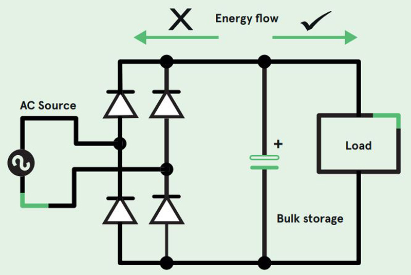
There is typically an energy storage element on a product’s internal DC line, such as a bulk ‘reservoir’ capacitor, potentially storing many joules of energy. For an AC-input product, the line rectifier isolates this capacitor from the input and the safety standards that mandate that the residual voltage on the AC terminals must fall to a safe value within one second can easily be met (Figure 2). Without a rectifier on a DC input product, an accessible connection could be at the full 385VDC and take a relatively long time to discharge internally. This poses a safety hazard, especially as the equipment connection will normally have exposed ‘male’ contacts. A solution is a series diode fitted internally to the product, but at the expense of extra power loss. The diode does also however provide reverse polarity protection. A MOSFET could be used as an isolator with low loss but this adds cost and complexity.
Click image to enlarge
Figure 2: AC input rectifiers isolate energy storage components from accessible connections
Another option for a building power bus is 24VDC, already common for sensors and control electronics in industry. This only suits low power equipment however, as, for the same power rating, current would be more than 15 times higher than with a 385VDC input. 24V is ‘Extra Low Voltage’ (ELV) however, which has the advantage that it is inherently a low risk for electric shock. Wiring also does not have to be installed by a certified electrician and it can be re-located cheaply and quickly. 24VDC could still supply dangerously high current, depending on the power source, leading to possible injury, overheating and fire, so installation practice and protection methods will become standardised. 24VDC will be useful for sensors, controllers, LED lighting, IoT nodes, and other low power electronics that may include internal DC-DC converters to generate end-voltages. It has been suggested that a USB-style 5V bus for device charging could be generated centrally from 24VDC or 385VDC and distributed through a building. This will not be viable however, as a USB-specification 5V must be quite accurate at the point of load, and surges, spikes and droops from resistive losses on the cabling would be unacceptable. Additionally, individual intelligent control of voltage and current sourcing is often required as in the USB-C standard, so realistically, we will still see individual 5V USB charge points, with 24V inputs rather than AC mains. As a consequence, they will be smaller, cheaper and without the issue of safety clearances, making them easier to integrate into connector wall plates.
Grounding is an issue
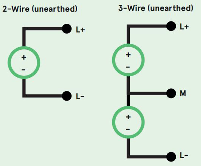
Home DC bus arrangements will need a defined relation to ground for functional and safety reasons; without a ground, connections could ‘float’ up to damaging voltages and produce electromagnetic interference at indeterminate levels from the numbers of connected switching DC-DC converters. An internal connection to ground may already be present in installed equipment risking unintended ground loops; for example, solar panels typically have grounded outputs as bought, so it is likely that a solid connection to a central ground will be defined in a DC building electrical system, similar to the way AC neutral connects to ground at a central point. The positive of a 48V bus is grounded In IT DC systems, thereby distributing -48V power. This prevents galvanic corrosion of ground connections in humid atmospheres. However, in controlled domestic and industrial environments, this is less likely to be of concern and a negative grounded/positive bus is likely to be the preferred solution, though there are other options (Figure 3). A positive bus also allows common, non-isolated ‘buck’ converters to be used to generate lower positive voltages. If the input were negative, the less common ‘buck-boost’ or other similar circuit would be necessary.
Click image to enlarge
Figure 3a: DC supply grounding option - option 1*
Click image to enlarge
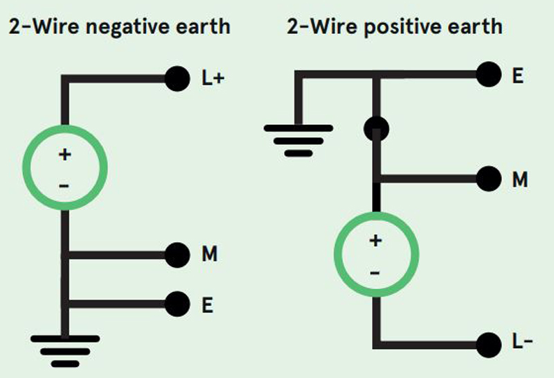
Figure 3b: DC supply grounding option - option 2*
Click image to enlarge
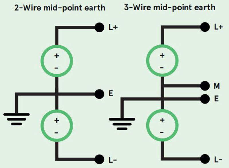
Figure 3c: DC supply grounding option - option 3*
*Image reproduced with permission from G KenyonTechnology Ltd and The Institution of Engineering and Technology