Author:
Bakul Damle, Business Management Director; Maxim Integrated, and Sagar Khare, Executive Business Manager, Battery Management; Maxim Integrated
Date
01/29/2021
 PDF
PDF
Click image to enlarge
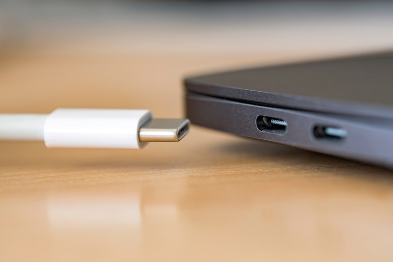
Figure 1. USB Type-C and USB Power Delivery are bringing the conveniences of fast data transfer and charging to portable devices
In devices operated by high-capacity 2S batteries, USB Power Delivery (PD) is a boon as it enables fast charging that gets these products back in operation with little downtime (Figure 1). Also, many applications that previously used AC-DC barrel adapters are migrating to USB PD for convenience and standardization. For designers, however, compliance with the USB PD standard typically requires complex firmware development and additional hardware components. With the short distance and high voltage (20V) between pins on the Type-C port, there are certainly opportunities for damage if the connector is inserted or disconnected at an angle. Indeed, both USB Type-C and USB PD specifications require hardware and software design expertise as well as advanced knowledge of the USB specification.
Consumer devices like cameras, AR/VR systems, and wireless speakers are leading the charge to USB Type-C and USB PD. Ironically, these are the very products that can ill-afford an extensive development cycle, given the time-to-market pressures. On the horizon, applications in areas like industrial and medical are on the cusp of greater adoption, as the same consumers are demanding the same level of convenience in their professional environments. We're also seeing the USB Type-C standard used in things like point-of-sale (POS) devices, industrial scanners, and breast pumps. In this blog post, we'll share some tips to streamline the design effort for USB PD designs.
Design Challenges of USB-C Charging Systems
USB Type-C and USB PD enable designers to realize the promise of a universal connector, providing the specifications for a reversible 24-pin connector for data transfer and power delivery. USB-C specifies 5V up to 3A (15W), while USB PD 3.0 specifies 5V to 20V up to 5A (100W). To design a charging system for USB-C, you'll need to:
Meeting these challenges typically requires complex host-side software development for USB-C negotiation, or additional parts such as external FETs and external microcontrollers. However, there are charging system solutions available that help minimize these challenges. One key feature is compliance with the protocols, as this will simplify the design implementation. Some solutions are also designed with event-based action scripts that make the customization process easier. Highly integrated ICs will eliminate the need for too many discrete components. Also, be sure to consider features that will help maintain reliable operation in harsh environments (varying temperatures or moist conditions, for instance).
Another consideration arises with the use of higher capacity batteries, which the power-hungry end devices need in order to support longer runtimes. Migrating from a 1S to a 2S battery increases the capacity without increasing the charging current. Since USB-C supports input voltages between 5V and 20V and 2S or 3S battery voltages fall somewhere in between, a buck-boost converter can help bridge the gap. See Figure 2 for a block diagram of a 2S battery-based application.
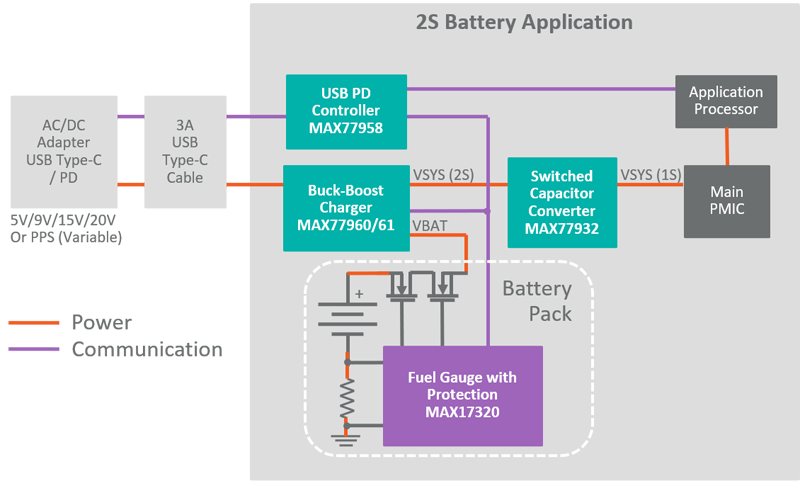
Click image to enlarge
Figure 2. Block diagram of a 2S battery-based application
Out-of-the-Box USB-C Compliance
Maxim Integrated has a new pair of USB-C charging system solutions that provide out-of-the-box compliance with the USB PD 3.0 specification, eliminating firmware development and reducing development time by up to three months. Their compact footprint also reduces the solution size by half compared to competitive solutions. The MAX77958 USB Type-C and USB Power Delivery charge controller is responsible for doing away with the firmware step, thanks to its GUI-driven customization script, BC1.2 support, and configuration settings related to Fast Role Swap (FRS), Dual Role Port (DRP), and Try.SNK mode. The standalone device eliminates an external microcontroller, provides out-of-the-box USB PD 3.0 compliance, and enables you to customize operation for the end application without firmware development. The device is also designed to withstand harsh environments via features including 28V rating, VBUS short protection to CC pins, an integrated analog-to-digital converter (ADC), and moisture detection/corrosion prevention.
The MAX77958 can autonomously control a companion charger through its master I2C interface. MAX77961 is a 6A buck-boost charger with integrated FETs for fast charging of high-capacity 2S and 3S Li-ion batteries. It provides a wide input voltage range (3.5V to 25V) for USB PD charging, requires no discrete FETs, and can be configured with or without an application processor. Peak efficiency is 97% at 9VIN, 7.4VOUT, 1.5AOUT.
You can evaluate both parts with the MAX77958EVKIT-2S6# (configured for 2S batteries) or MAX77958EVKIT-3S6# (configured for 3S batteries), which demonstrate the MAX77958 autonomously controlling the MAX77961 charger with its I2C master feature.
These devices are part of a broader portfolio of USB Type-C and USB PD devices that includes power-efficient chargers and converters, autonomous and robust controllers, and power path and protection ICs.