Accurate automotive liquid-level capacitive sensing
Designing a precise and robust liquid-level sensing solution for vehicle systems using capacitive sensing technology
Monitoring fluid levels efficiently and accurately has been a challenge to automotive engineers for a long time. While knowledge of the fuel level is important to the driver, there are other fluids the vehicle itself needs to monitor, such as motor oil, brake fluid, and battery fluids. Many cars have also started to measure exhaust fluid.
Diesel exhaust fluids are mostly used in trucks (or other diesel vehicles) to help them reduce their emissions. Fluid is sprayed into the exhaust of diesel vehicles (after the diesel has been combusted) to help convert oxides of nitrogen into harmless gas and water vapor, thereby reducing emission levels. This is becoming increasingly popular in the automotive industry owing to the recent Volkswagen emissions scandal. We may start seeing these Diesel Exhaust Fluids (DEFs) become a standard requirement in all diesel vehicles in future. The EU is already mandating that OEM manufacturers use DEFs. It is estimated that by 2020 about 10M of all the vehicles in the world will be using DEFs.
The DEF is stored in a separate tank from the fuel tank and away from the engine. It is important to monitor the level of this fluid. In this article, we will explore the current technologies used to sense fluid levels in automotive applications, the challenges associated with each of these technologies, and how capacitive sensing enables robust monitoring.
Current technologies:
There are several different technologies that exist today to measure the fluid levels in a tank, including:
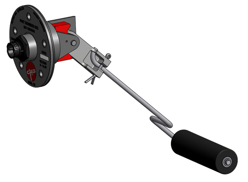
-Mechanical floats/switches: These are the oldest type of fluid sensors. Mechanical sensors are single/multi-point level switches and continuous level transmitters (see Figure 1).
Click image to enlarge
Figure 1. Mechanical Float switch
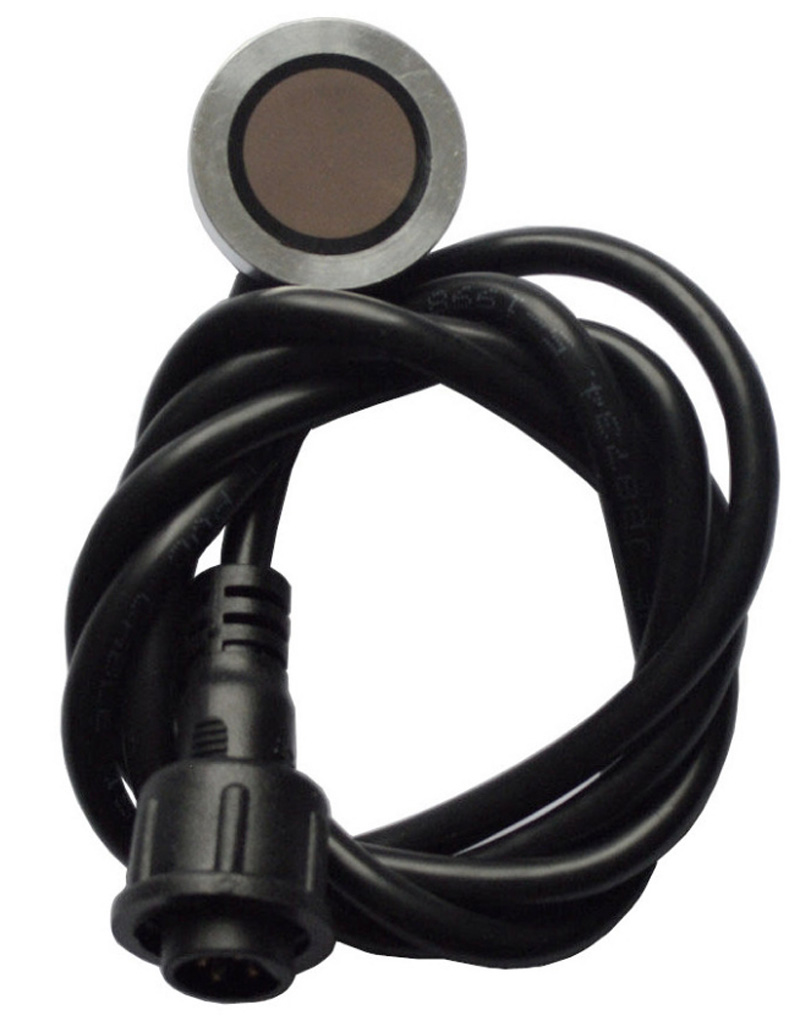
-Ultrasonic: An ultrasonic sensor measures the time interval between an ultrasonic signal that is sent and received. The delay is used to calculate the fluid level. Ultrasonic sensors are mounted on the bottom or top of the tank. This is one of the more accurate methods of level sensing for fluids (see Figure 2).
Clickimage to enlarge
Figure 2. Ultrasonic Liquid Level Sensor
-Pressure-based: The level of liquid in a container can be measured using a pressure sensor. The sensor is placed at the top of the tank and is connected to a tube that is inside the tank. The amount of fluid in the tank exerts a proportional amount of pressure on the sensor via the compressed air in the tube. The sensor produces a pressure equivalent voltage, which can then be converted to a digital signal for processing and evaluation.
Challenges
Conventional level sensors based on floats only deliver approximate fuel level information at a relatively high cost. They cannot provide other useful information such as fuel quality, temperature, and concentration information. With a capacitive sensor, however, it is possible to measure other properties than fuel level by following simple guidelines. In this article we will focus solely on level sensing.
Capacitive sensing for fluid-level sensing
Capacitive sensing is a well-established technology enjoying widespread use in touch-based user interfaces. Although predominately used for interface related features, capacitive technology can also be used to detect fluid levels as well.
Capacitive sensing technology measures either a change in capacitance between a sensor and parasitic ground (self-capacitance measurement) or a change in capacitance between two sensor pads (mutual capacitance measurement). With a self-capacitance measurement, electric fields originate from the sensing electrode and end in the nearby parasitic grounds. When these fields are disturbed by the presence of any dielectric/conductive materials, self-capacitance between the sensor and ground is altered and the measured capacitance changes.
Mutual-capacitance measurements depend mainly on the capacitance between two electrodes (Tx and Rx). The effect of parasitic capacitors to ground is not much of a problem, though it will require higher Tx drive strength. Thus, mutual-capacitance measurements can distinguish even smaller signal changes in the presence of higher parasitic capacitance easily and it will make the design more robust than measurements made using self-capacitance.
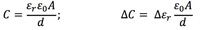
Dielectrics with higher relative permittivity will increase capacitance. Different liquids with different relative permittivity constants will change capacitance in different ways.
Different types of layouts are discussed below in order to build out a capacitive-based sensing solution.
Layout guidelines
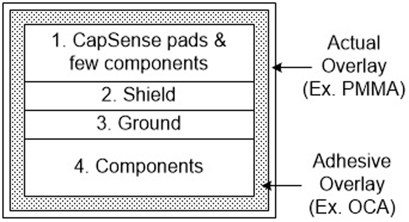
In Figure 3, four layers of PCB are shown. The top layer contains the capacitive sensor pads. A capacitive-sensing controller such as Cypress’ PSoC 4 device can be placed on either the top or bottom layer, depending upon the form factor of the board. A shield layer serves as the second layer, and the third layer acts as ground.
 \
\
Click image to enlarge
Figure 3. Cross Section of the PCB showing different layers
The shield layer ensures that electric fields from capacitive sensing pads don’t terminate within the PCB grounds. It helps in diverging the fields in order to detect changes in the environment (presence or absence of liquid). The shield is a buffered version of the sensor switching signal with the same amplitude, frequency and phase as that of the sensor signal. The shield also helps in reducing overall parasitic capacitance. You can refer to Getting Started With Capacitive Sensing to understand more about the details of designing with capacitive sensing technology.
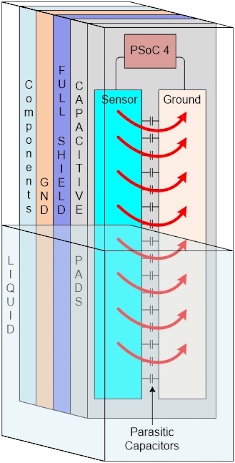
Figure 4 shows a simple layout example of a liquid sensing design. The fluid acts as an additional dielectric for the parasitic capacitors between the sensor and ground pads. Thus, the effective capacitance is modified by the presence of liquid. The exact level of the fluid inside the tank can be accurately calculated by measuring the change in “raw counts”.
Click image to enlarge
Figure 4. 3D view of Full PCB placed inside a tank showing different layers
Raw counts are the digital counts corresponding to the sensor’s capacitance. Baseline counts (i.e., a filtered version of the raw counts) track slow changes to the environment. The difference between the raw counts and baseline counts is called the Difference counts and is directly proportional (i.e., linear relationship) to changes in capacitance.
In this design, the absolute value of self-capacitance (Cp) could be very high (>50 pF) in case of large tanks (>10cms). This can make detecting a small change in capacitance (~100 fF) difficult. By splitting the sensor into multiple individual sensors, we can reduce the absolute value of self-capacitance to increase sensitivity. Here, sensitivity is the ratio of change in self-capacitance to the absolute value of self-capacitance.
If the absolute value of self-capacitance is reduced, this ratio will become larger. This makes the signal easier to measure. Alternatively, the signal can be measured with a lower resolution Sigma Delta converter. Figure 5 shows a layout pattern that avoids the problem of higher Cp. However, we still have two issues to resolve with this pattern.
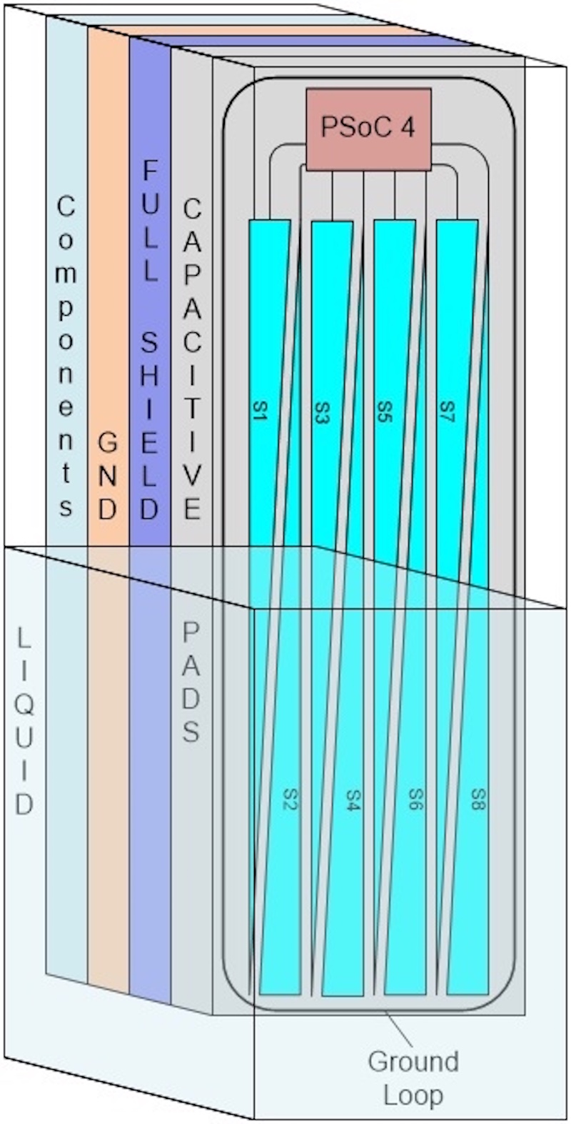
Click image to enlarge
Figure 5. 3D View of Tooth based layout of the sensor placed inside a tank
Be in phase
There could be a significant difference between the phase of the excitation signal at the top of the sensor and the bottom of the sensor. This could reduce the effectiveness of the measurement. At any point of the sensor, both shield and sensor pads should be in phase with each other.
If used in larger tanks, the sensor area would become very large as well. This leads to higher Radiated Emissions (RE) that are very important in meeting Automotive EMC standards (such as CISPR-25). Even though the second layer of the PCB is a shield layer, large sensors can still cause higher emissions. Individual shields, a better solution to avoid these problems, are shown in Figure 6.
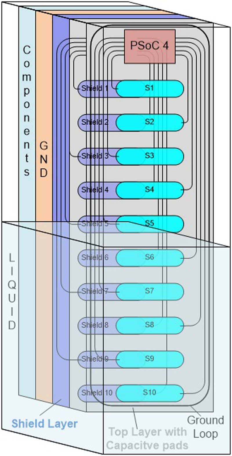
Click image to enlarge
Figure 6. Individual Shields
This pattern splits a large, single sensor into small individual sensors with corresponding shields in the second layer. Figure 7 shows the front view of the sensor pattern.
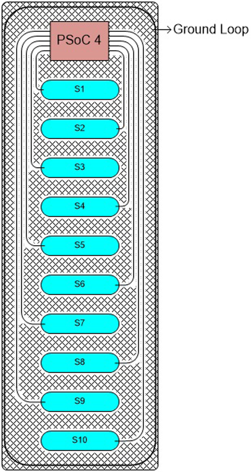
Click image to enlarge
Figure 7. Front view of the sensor pattern
Capacitive sensing controllers such as Cypress’ PSoC 4 provide automotive qualified (AEC-Q100) capacitive sensing capabilities that are also available with extended temperature range operation as well. PSoC stands for Programmable System On-Chip and features an ARM Cortex-M0 core, capacitive sensing block (CSD), and programmable analog and digital blocks that provide flexibility in designing application.
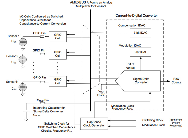
Figure 8 shows a block diagram of a capacitive sensing-based system. The PSoC 4 CSD block uses two IDACs (compensation and modulation) to reduce the absolute value of parasitic capacitance Cp as well as to handle the variation of Cp across different sensors.
Click image to enlarge
Figure 8. Block diagram of CSD (Capacitive Sigma Delta) block
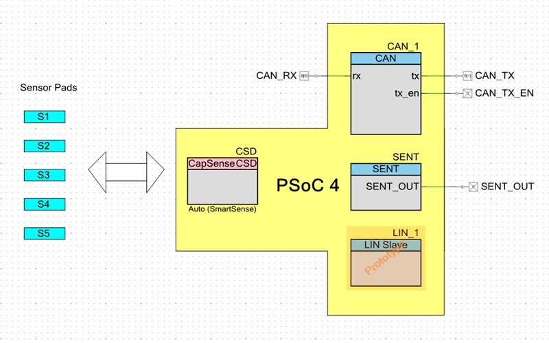
Figure 9 shows the application-level block diagram including the CSD component for capacitive-sensing. Also shown are standard automotive communication interfaces such as CAN, SENT, and LIN for communication with the ECU controllers. SENT (Single Edge Nibble Transmission protocol) is a very low speed one-way interface used mainly in automotive sensors.
Click imagem tom enlarge
Figure 9. TopDesign schematic view in PSoC Creator
Cypress provides PSoC Creator software to assists developers in putting components together and programming them. To further enhance the capabilities of capacitive sensors, developers can use SmartSense technology to tune capacitive sensing parameters automatically. This simplifies design as well as enables OEMs to bring design to market more quickly.
To detect the level of the liquid in the tank, we can use ratio metric methods. One sensor at the bottom of the tank serves as a reference electrode. The presence of liquid is detected only by monitoring the other electrodes. Another option is to monitor the difference between two difference counts of electrodes sequentially (S1-S2, S2-S3, S3-S4, etc.).
Other considerations
Different liquids used in automobiles have different freezing points. For example, DEF has a freezing point of about -11˚C. Hence, it is possible for such liquids to freeze in many parts of the world during winter. Conventional liquid sensing methods such as mechanical and ultrasonic fail in frozen conditions. Capacitive sensing-based liquid sensing, however, is robust even under such harsh operating conditions.
Where an essential fluid like DEF is frozen but required for driving, heating elements can be placed inside the tank. When the automobile is started, this tank can be heated up to bring the fluid to a liquid state. When the tank is large (i.e., >10cms), the distribution of temperature across different parts of the sensor pads could also be different. Baseline counts tracked for individual sensors helps in handling the variation of temperature across different sensors.
Performance can also be improved by having a thermistor inside the tank to monitor the temperature. The same controller used to monitor the sensor can use the raw counts to compensate for temperature variations using pre-defined values.
Squelching is another common problem in automobile tanks. Squelching refers to the fact that the level of liquid does not remain stable during driving conditions. For example, it could have wave patterns while driving and will tilt towards one direction when driving on slopes. Accuracy with a capacitive-based sensor can still be maintained by measuring the centroid using the multiple individual sensors available and preciously determine the liquid level.
Impurities in the fluid can change the dielectric and conductive behavior of the fluid. Changes in the overall dielectric properties of the liquid lead to changes in the raw counts compared to pure fluids at the same temperature. Note that this change in raw counts will be seen across all the sensors monitoring the fluid. By collecting the raw counts across different impurities, a Look-Up Table (LUT) can be built to determine the purity of the liquid. This information can then be used to compensate for the impurities. Based on the variation of raw counts/difference counts of different sensors, impurities in the liquid can also be monitored using statistical models.
Capacitive sensing provides an accurate and robust way to sense liquid levels. It overcomes many of the issues that arise with conventional level sensing approaches and provides developers with the flexibility to introduce enhanced functionality, such as being able to accurately measure the level under freezing conditions.