Using an intelligent hot-swap controller for optimal performance
The term “hot swap” refers to the practice of inserting or removing modules from a powered system. Hot-swap controllers are sometimes categorized together with power distribution switches; however, there are key differences that must be understood for proper system design. A hot-swap controller uses an external series-pass transistor to limit inrush current. An integrated hot-swap device includes both a controller and a series-pass transistor in the same package.
Both controllers and devices usually implement overload protection as well as inrush control. These features require current measurement. Many newer hot-swap products report current, voltage and power usage either as analog outputs or digital values accessible across a data bus. The ability to accurately measure current, voltage and power usage offers system designers an opportunity to implement current and power reporting, which can increase the design’s usefulness and robustness.
Power-distribution switches resemble hot-swap devices without inrush control. They still incorporate current sensing, and some include a current-monitoring pin.
Recent trends in hot-swap products include improved current-sense accuracy, increased integration and higher load currents. Many modern hot-swap products have current-sense accuracies of ±2 percent or better. Higher accuracies allow smaller design margins and therefore enable the system to draw more power from a given supply. Higher integration provides many benefits, including digital-communication protocols and built-in load-management functions.
System description
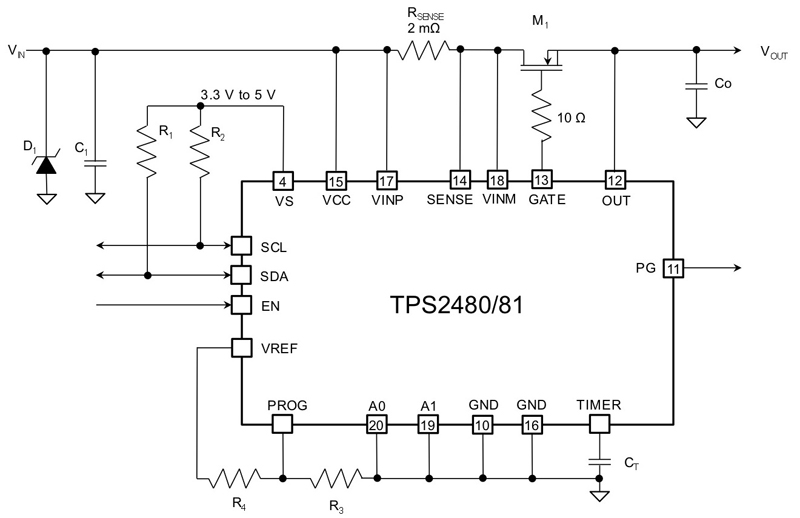
Hot-swap and power-distribution switches support a range of applications and therefore offer a wide variety of features. Figure 1 illustrates a typical application that includes input-voltage surge protection, programmable power-limiting, precision load monitoring and reporting, an integrated analog-to-digital converter (ADC), digital communication via I2C, and of course, programmable fault management.
• Voltage surge protection improves the robustness of a circuit against transients on the AC mains, with increased protection closer to the AC mains.
• Programmable power-limiting controls the series-pass metal-oxide semiconductor (MOS) transistor during inrush to ensure that it remains within its safe operating area (SOA). This power-limiting feature permits the use of smaller and cheaper MOS transistors without sacrificing reliability.
• Precision load monitoring reports current, voltage and power information, either as analog output signals (Figure 1) or via digital communications. A system controller can use this information to implement a variety of features such as intelligent power allocation across multiple systems, or predict emerging faults based on anomalous power consumption.
• Programmable fault management includes such features as power-good indicators for power sequencing, undervoltage / overvoltage protection, and overload protection.
The above features provide an additional layer of security beyond that which is implemented within the system controller. Most high-reliability products require this level of protection to guard against the possibility of firmware upsets within the system controller.
Click image to enlarge
Figure 1: Typical hot-swap controller that includes precision monitoring
Sensing implementations
Methods employed to measure current include integrated and discrete sense resistors, ratiometric MOSFETs, and Hall effect sensors. Factors to consider when comparing these approaches include current and power levels, board area, efficiency, accuracy, and isolation requirements.
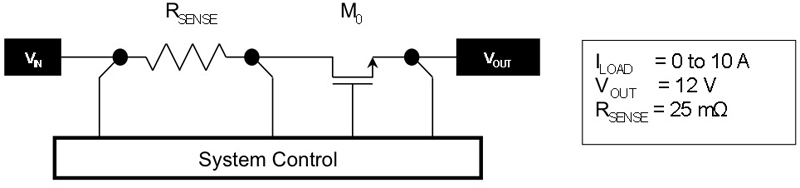
The simplest current sensor is a resistor. Consider the circuit in Figure 2. Current flows from VIN through the sense resistor, RSENSE, and pass transistor, M0, to VOUT. Separate voltage-sensing leads ensure accurate measurement of the voltage drop across the resistor. This arrangement is sometimes called four-wire sensing or a Kelvin connection.
Click image to enlarge
Figure 2: Sense-resistor implementation
The magnitude of the sense resistance represents a compromise between accuracy and efficiency. Suppose the system control block in Figure 2 has a maximum input-referred offset voltage of ±2.5 mV. A 25-mΩ sense resistor will develop 250 mV at 10 A while dissipating 2.5 W. Input offset will generate a ±1 percent error at 10 A, or a ±10% error at 1 A. As this example suggests, it is difficult to obtain high accuracy at low currents without dissipating excessive power at high currents.
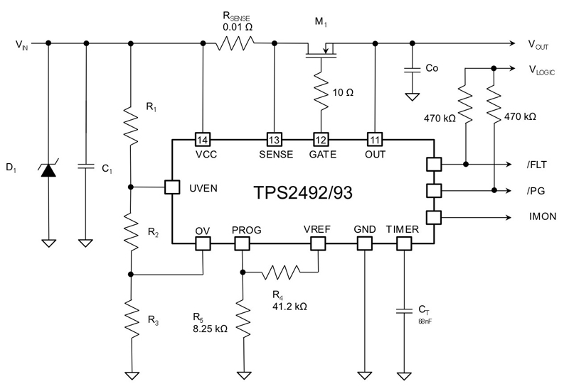
Figure 3 shows a typical application circuit employing a discrete RSENSE. The use of a discrete resistor allows you to use the same controller in multiple system designs, but this flexibility comes at a cost. A discrete resistor costs money, dissipates power, and occupies board space.
Click image to enlarge
Figure 3: Sense-resistor implementation and current monitor
An integrated sense resistor reduces printed circuit board complexity, size, and cost. An integrated resistor, however, may not offer the same precision or power rating as its discrete counterpart. Furthermore, the elimination of the external component reduces flexibility unless the integrated circuit (IC) includes some form of programmability.
Ratiometric sense transistors minimize power losses at the cost of inserting another potential source of inaccuracy. A tiny fraction of the load current flows through a small sense transistor connected in parallel with the large pass transistor. Only the current flowing through the sense transistor must pass through a resistor. The larger the ratio between the main pass transistor and the sense transistor, the smaller the power loss. Practical designs usually use ratios between 100-to-1 and 10,000-to-1. The larger ratios typically involve some loss of accuracy, due to matching errors between the main pass transistor and the sense transistor.
Some devices, like the TPS2520 hot-swap controller, use a combination of an integrated ratiometric sense transistor and an integrated resistor to provide current sensing. This arrangement saves board area and eliminates the cost of discrete components. Other devices such as the TPS2552 and TPS2553 power-distribution switches use an integrated ratiometric sense transistor and an external discrete resistor. This arrangement offers increased flexibility at the cost of one small and inexpensive surface-mount resistor.
Inrush control, current and power limiting
Hot swapping enables the replacement of components without interrupting system operation. Each component contains a hot-swap controller that protects the system during a hot-plug event. The hot-swap controller uses a pass transistor that limits inrush current to avoid damaging connectors or causing power supplies to sag below their undervoltage-lockout (UVLO) thresholds.
The simplest inrush control scheme uses a constant current to charge load capacitance and provide startup current. The hot-swap controller monitors the load voltage. If this voltage does not reach operational levels within a set period of time, the controller turns off the power transistor to prevent it from overheating. Typical hot-swap controllers use external components to select both the inrush current and time.
Once inrush is complete, the hot-swap controller fully enhances the pass transistor to minimize power dissipation. The controller continues to monitor the load current, and if it exceeds a predefined current limit, it disables the pass transistor. Modern hot-swap controllers often implement two current limits: a lower one that causes a shutdown only if it persists for a predefined length of time, and a higher one that immediately shuts off the pass transistor. This arrangement permits a load to draw brief surges of current, while preventing gross faults from causing system disturbances.
Some hot-swap controllers implement power limiting to provide an additional level of protection during startup. Power limiting ramps up the load current as the drain-to-source voltage across the pass transistor diminishes, keeping power dissipation within the transistor constant. This ensures that the transistor provides the maximum possible inrush current without violating its SOA.
Data collection, reporting and dynamic configurability
While capable of autonomous operation, hot-swap controllers become much more valuable when they can communicate with a larger system. “Intelligent” hot-swap controllers can report parameters such as load current, input and output voltage, and load power. The system can also use the hot-swap controller to enable or disable subsystems. Designers can harness these benefits to offer additional features and improve system robustness.
The capabilities of intelligent hot-swap devices vary significantly. For example, the devices shown in Figure 3 are fairly simple hot-swap controllers that provide an analog voltage proportional to the load current at the IMON pin. Systems that include an ADC can use the IMON output to track load current and calculate load power.
Like most hot-swap controllers, these devices also provide digital outputs indicating overcurrent and power-good conditions, as well as an enable input that enables the system controller to disable or restart faulted loads, sequence the startup of downstream power converters, and manage system power across many different loads.
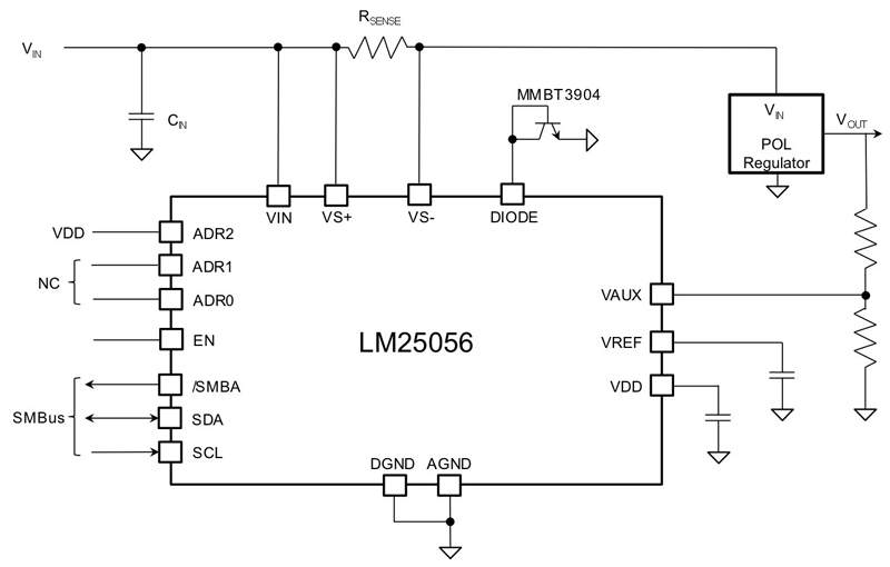
A system communication bus such as I2C or PMBus allows sophisticated dynamic configuration and monitoring of multiple devices. The TPS2480 integrates a precision ADC that can report the input voltage, load current, and power through an I2C bus. The system power-measurement IC in Figure 4 supports PMBus reporting of numerous quantities, including voltage, current, power, and temperature. Used in conjunction with an appropriate hot-swap device, the power management IC with PMBus provides the capability to safely monitor and configure multiple loads.
Click image to enlarge
Figure 4: Integrated hot-swap device with monitoring and configurability
Recommendations
Typically, a hot-swap controller or integrated hot-swap device resides where subsystems connect together; for example, where daughtercards plug into a motherboard, or where data and power cables connect to mobile devices. Due to their location between subsystems, hot-swap controllers and devices are often subjected to unusual transients and system-level electrostatic discharge (ESD) events.
Designing a reliable system requires understanding the nature of these abnormal conditions. Consider whether an intelligent hot-swap device is required, and if so, what capabilities it must possess. Although intelligent hot-swap devices are more complicated and costly than simple autonomous hot-swap controllers, they provide additional functionality that may reduce overall system complexity and cost.
When selecting an integrated hot-swap device, pay close attention to the performance of the current-sensing circuits. Do not rely merely on nominal specifications, but look at maximum and minimum data-sheet limits over temperature. Consider not only the accuracy of the current-sense circuit at full scale, but also at lower current levels.
Also note that some ratiometric current-sense schemes may exhibit a discontinuity between normal operation and current limit. Such devices typically allow the current to rise to a maximum level, and then snap back to a lower current limit. A DC sweep of load current quickly reveals whether or not a given device exhibits peaking.
You can often choose between an integrated hot-swap device and a hot-swap controller that uses an external power transistor. Higher current levels dictate the use of external power transistors due to heat dissipation.
Looking forward
In this article, we discussed options for implementing accurate current and power monitoring using hot-swap controllers and devices. Overlooking the design of adequate transient protection and load management early in system development may result in damaged boards and devices during qualification or cause production delays.
Current, voltage and power measurement and reporting can improve system reliability and enable power management and negotiation. Integrating accurate measurement of current, voltage and power usage can differentiate your system design in terms of customer access and control, as well as reduce customer interruptions and field failures.