Accurate Current Sensing for Next-Generation EV Designs
Accurate information about current flow is essential to improve the performance of EVs in many areas
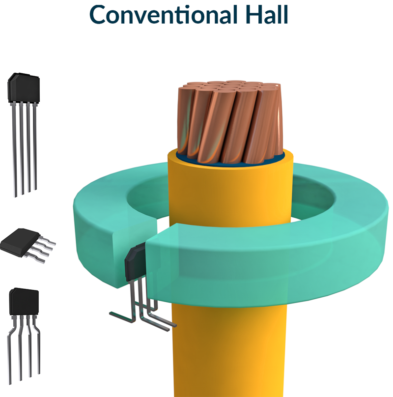
Figure 1. Conventional Hall sensor in concentrator air gap
Automotive manufacturers need to enhance the performance and capabilities of their electric vehicle (EV) models to differentiate and attract buyers to switch from conventional vehicles. Reliability, extended driving range, and safe fast-charging are important buying criteria that can be improved with precision current sensing in key areas of the powertrain.
Accurate current sensing in automotive
Major subsystems of modern vehicles, such as steering, braking, and lubrication and coolant pumps, have become electronically controlled. This trend has brought numerous improvements including weight savings, fuel economy, affordability, performance, and safety. Now, battery-electric and fuel cell vehicles are taking electrification to its ultimate conclusion, replacing the combustion engine and fuel system with an electric motor and a battery system.
Accurate data about the current flowing through power supplies, converters, and motor windings is critical for maintaining control. Current monitoring is also essential for fault detection and diagnostics, to indicate a defect such as a short-circuit, broken connection, or jammed motor. In the battery management system (BMS), current sensing is vitally important for condition monitoring and cell balancing to ensure reliability and safety, while the onboard charger (OBC) needs accurate real-time current measurement to assess the battery state of charge and control the charging session.
Throughout an entire vehicle infrastructure, current monitoring is needed in a wide range of conductors, large cables and busbars carrying currents ranging from tens to hundreds of Amps to narrower wires and PCB tracks carrying just a few Amps or less. While the accuracy needed can depend on the application, a fast response is almost always required, particularly for real-time control. Moreover, space is typically at a premium in today’s vehicles, so that large and bulky sensing solutions are not practicable. Also, there is constant cost pressure in automotive markets and car makers are under pressure to deliver affordable EVs. Hence, an inexpensive bill of materials and easy and fast assembly on the production line are also key requirements.
Current sensing with shunts
Inserting a shunt resistor in series is a way of measuring current flow. A low and precisely known value of resistance is placed in the high-side circuit between the battery and the load. Alternatively, it can be inserted in the low side where one terminal of the resistor is connected to the load and the other is connected to ground.
Measuring the voltage drop across the shunt resistor (RShun) enables the current (I) flowing through it to be calculated easily based on Ohm’s law:
V2 - V1 = RShunt x I
The two voltages are fed into a difference amplifier and then typically into an A/D converter. The output from the converter provides an indication of the current, which can be made available to the application software.
This approach is easy to implement and is suitable for measuring AC as well as DC currents. The strength of shunt measurements is their linearity and their intrinsic immunity to stray magnetic fields. On the other hand they still need compensation for temperature changes. With higher current, a smaller shunt resistance is needed to manage heat dissipation. Also, if galvanic isolation is required, extra components are needed to implement it.
Hall-effect current sensors
Hall-effect current sensing is an alternative approach that takes advantage of the fact that passing an electric current generates a magnetic field around the conductor. In the absence of ferromagnetic concentrator, the magnitude of the field strength (H) is proportional to the current (I) and reduces with increasing distance (r) from the conductor, as expressed here:
H = I/(2πr)
Knowing that the field strength is related to magnetic flux by the equation:
B = μ0 x μr x H
It follows that:
B = μ0 x μr x I/(2πr)
Where μ0 (permeability of free space) = (4π x 10-7), and μr is relative permeability (both dimensionless constants)
The Hall sensor responds to magnetic flux and generates a proportional output voltage.
Hall-effect sensing has several advantages over sensing with a shunt resistor. While there is negligible voltage drop or concern about power loss, galvanic isolation is implicit. As with a current shunt, Hall-effect sensing can be used for both AC and DC measurement.
Conventional Hall current sensor
These current sensors are sensitive to the magnetic field perpendicular to the chip surface. They are meant to be used in combination with a ferromagnetic core. In a typical application, the core is wrapped around the current-carrying conductor and concentrates the magnetic flux in a small air gap (typically 2-5mm) where the sensor is inserted.
● Isolated currents up to 2000A
● Core for signal concentration
● High stray field immunity
● Robust against mechanical play
In addition to the air-gap length, the core material, core dimensions, and core geometry all influence the efficiency of the core and must be considered when choosing or designing a suitable component. Fortunately, an alternative is now available that allows a simpler approach. Melexis provides a conventional Hall core development kit that contains various sensors and cores with different air-gap sizes, which users can combine to achieve their desired current-sensing range.
Click image to enlarge
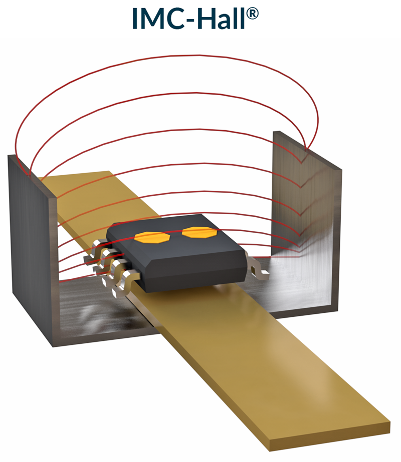
Figure 2. Hall sensor with IMC (yellow discs), stacked over current-carrying busbar and shield
IMC-Hall current sensors
Thanks to patented integrated magnetic concentrator (IMC) technology, IMC-Hall sensors are sensitive to magnetic fields parallel to the chip surface. Thus, the sensors can directly measure the current flowing in a bus bar or a PCB trace below the package, without the need for a core.
● Isolated currents up to 2000A
● Shield and internal magnetic concentrator (IMC)
● Easy assembly & vertical stacking
● Robust against mechanical play
Melexis provides an IMC Hall sensing development kit that comprises circuit boards containing various sensors and a selection of ferromagnetic shields to ease component selection and evaluation.

Click image to enlarge
Figure 3. Isolated integrated current sensor
Integrated primary current sensors
Unlike most current sensors, the integrated primary current sensor does not rely on ferromagnetic concentrators. Instead, it uses an internal differential sensing concept to detect the magnetic field that is generated by the integrated primary conductor. This differential concept also provides a high level of stray field immunity, enabling higher density power electronics, as the sensor is less affected by stray magnetic fields in close proximity.
● Internal conductor up to 50A
● No magnetic hysteresis
● No customer calibration needed
● Up to 4.8kV isolation
Conclusion
The rapid pace of automotive electrification has increased demand for accurate current sensing to manage major subsystems in conventional and hybrid/electric vehicles. Hall-effect current sensors deliver flexibility and ease of use and eliminate the voltage-drop and power-dissipation concerns associated with current sensing using shunts.
A broad choice of Hall sensors is available, including conventional devices to be used with a magnetic concentrator, IMC sensors that require a simpler magnetic shield and allow surface-mount assembly and integrated primary current sensors which simplify the system design. In-sensor signal processing relieves circuit design and layout challenges and can help minimize the overall footprint and bill of materials, which are important considerations for automotive manufacturers.