ADC Selection for Partial Discharge Pulse Analysis in High-Voltage Power Systems

Partial discharge in high-voltage distribution equipment occurs in power cables, transformers, switchgear, bushings, motors, and generators
Figure 1: showing the pulse characteristics of a partial discharge, with the void capacitance rapidly releasing charge before the electric field collapses locally, and a fast current spike flows
Partial discharge in high-voltage distribution equipmentcan be used as an early warning indicator of insulation degradation and eventual failure, and without detection, can evolve into complete dielectric breakdown, arc faults, and potentially explosive equipment failure.
If partial discharge goes unmonitored, the consequences can compound over time, with the progressive erosion of insulation that will eventually lead to full dielectric breakdown. If uncontrolled, this can result in cable termination explosions, transformer winding faults, and bushing flashover. And these failures are often both sudden and violent.
Even in the best-case scenario, the accelerated aging of the insulation will cut years from a transformer’s service life, and cable systems will require premature replacement, with assets losing reliability margins long before visible failure appears.
The effect of this can be emergency replacement costs running into the millions of dollars and unplanned downtime for utilities and customers… plus regulatory fines. Indirect costs include loss of customer trust, brand damage, potential decline in company valuation, and increased audits or investigations that may disrupt ongoing operations.
Causes and Physical Mechanisms of Partial Discharge
Partial discharge occurs when localized electric fields exceed the dielectric strength of an insulation, but not by enough to completely bridge the insulation between conductors. It can be over a small region, or along its full length and is almost always associated with insulation defects or electric field enhancement.
There are several potential causes, and can be introduced at manufacturing, from the environment or simply through thermal, mechanical or electrical stress. For example, if air pockets within solid insulation are present, this can concentrate the electric field allowing ionization and repetitive micro-discharges each time the field exceeds the breakdown strength of air.
Environmental causes can include surface contamination (dirt, moisture, salt deposits) that create conductive paths along the insulation surface and allows progressive erosion. As for stresses, thermal cycling may cause delamination, mechanical stress can create microcracks, and chemical aging reduces dielectric strength.
And then there’s electrical overstresses such as lightning strikes, switching surges, and harmonic distortion increase insulation stress, trigger discharge in weak regions, and accelerate existing defects.
Also worth mention is geometric field enhancement, where sharp points, poor termination design, manufacturing defects, or damaged shields intensify electric fields and lead to corona discharges.
Electrical Pulse Characteristics
The typical characteristics of a partial discharge include a rise time of just a few nanoseconds, and potentially less than 1 ns. And while the pulse widths will be system dependent, these will typically be between 5 and 100 ns. And there will be a fast leading edge, and an exponential decay tail.
More specifically, the pulse behaves like a very fast impulse current that is followed by damped oscillation caused by the system’s inductance and capacitance and during discharge, the void capacitance rapidly releases charge, the electric field collapses locally, and a fast current spike flows – as we can see in figure 1.
With the pulse frequency spectrum extending from hundreds of kilohertz into tens or even hundreds of megahertz sensors used to monitor partial discharges need to have a high high-bandwidth, with fast ADC sampling and need to carefully design anti-aliasing filters.
Of course, for AC systems these partial discharge pulses often occur near voltage peaks and will often repeat at similar phase angles each cycle, leading to phase-resolved partial discharge (PRPD) patterns, which can be used for defect identification.
Testing has evolved significantly, and power networks have moved away from scheduled offline testing, which was highly labor-intensive (and therefore costly), and could only give infrequent snapshots of the system’s health. This has been replaced with permanently installed monitoring systems using a distributed array of sensors to allow for the continuous monitoring and therefore significantly reduces the likelihood of catastrophic failure.
The pulse shape determines many elements of a sensor network, from the required front-end bandwidth to the apparent charge calculation accuracy, and the interleaving mismatch sensitivity. And if system bandwidth is insufficient, peak amplitude is reduced, charge integration becomes inaccurate, and small partial discharge events may go undetected.
Crucially, the pulse shape also dictates the impact of digital filtering and the required sampling rate of the ADC.
Click image to enlarge
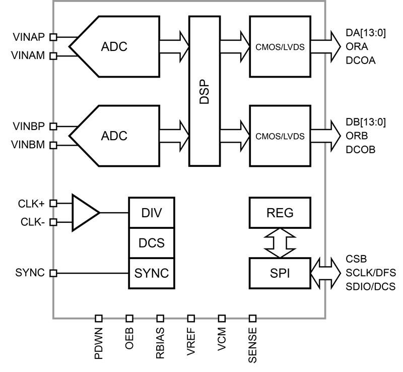
Figure 2: Silanna’s 14-bit, 170 MSPS SD1148ET-170 has an ENOB ≈ 11.7, an aperture jitter ≈ 140 fs and analog input bandwidth ≈ 650 MHz
ADC Selection for partial discharge Measurement
The ADC is the circuit component most critical for characterizing and analyzing these pulses, and getting selection right is vital. And while there is no universal “best” ADC, steps can be taken to ensure the right ADC is chosen for the specific sensor network.
Specifically, ADC selection depends on the sensor type and system requirements, with designers needing to balance a plethora of tradeoffs, including bandwidth, resolution, power consumption, cost, data rate, and noise immunity.
Regardless of these tradeoffs, ADC must take into account a handful of key parameters if it is to accurately capture partial discharge characteristics. These include the peak amplitude, the rise time, the pulse area, the timing accuracy and the repetition pattern. And distortion of any of these will reduce diagnostic accuracy and may allow early insulation failure to go undetected.
This balance can be seen if we examine a high-frequency current transformer (HFCT) used to monitor multiple partial-discharge locations within a substation. Typically, these will be required to measure signals from approximately 100 kHz to 50 MHz and to manage this, such a sensor would be expected to require an ADC an effective number of bits (ENOB) over 11, and aperture jitter that is sub 300 fs, and an analog input bandwidth that is over 100 MHz.
It should be noted that these sensor networks need to operate in noisy environments and will benefit from oversampling combined with decimation to improve signal-to-noise ratio. Additionally, features such as digital down conversion can be used to isolate frequency bands of interest, interleaving correction will help reduce mismatch artifacts and an increased timing precision will enhance phase-resolved partial discharge pattern accuracy.
Traditionally FPGAs have been used to manage these tasks and enable the low aperture jitter needed for the high signal-to-noise ratio needed for detecting the low-magnitude partial discharge events.
However, it is also possible to undertake these tasks via an integrated DSP within the ADC, and doing so can reduce the processing burden on downstream FPGAs and allow for smaller, lower-cost FPGAs without compromising data integrity.
Finally, it’s worth noting that pulse sensors will operate across a range of environments that are far from ideal, with switchgear cabinets often experiencing incredibly high temperatures and outdoor transformers being exposed to both direct sunlight and freezing winters. This may make standard commercial ADCs (rated for operation from -40oC to +85oC) potentially ill-suited and a broader temperature range, or even a MIL-TEMP specification (-55oC to +125oC) ADC may be required.
Conclusion
Partial discharge pulse monitoring crucial to the functioning of power networks, but the efficacy monitoring sensor networks undertaking it will only be as good as the data they capture. These need to implement high-bandwidth, low-jitter ADC architectures that can withstand extreme environments and detect and quantify even the most subtle events with precision.
There is no universal best device, but by prioritizing the right parameters and understanding the specific pulses that will be encountered it is possible to create the basis for detection and predictive maintenance that will not only prevent catastrophic failure, but also extend the operational life of critical infrastructure, and ensure the long-term stability of the power grid.