Replacing electromechanical components with a display need not be difficult
Replacing multiple electromechanical and optoelectronic elements with a touch-sensitive LCD can significantly extend a product’s lifetime. It could also reduce the overall size of the product, particularly if the space required for the PCB is much smaller than that used for the electromechanical controls. Given that microcontrollers today can integrate a wide range of functions and I/O in a package that measures just millimetres on each side, while the size of a switch hasn’t really changed in decades, this is probably the case.
If the intention is to upgrade from an electromechanical user interface to a touch-sensitive LCD, it is necessary to consider the feasibility of this in terms of the type of controls that need to be incorporated. This could be in the form of a direct, one-to-one replacement of conventional switches, buttons and sliders, but it could extend to rotary switches or keyboards, and even other forms of displays such as LEDs.
Of course, it may be necessary to add some components as part of the migration. For example, an electromechanical switch may need to be replaced by a latching relay; each application will be different, as will the approach to the design. Microcontrollers, or MCUs, are capable of handling the vast majority of an application’s functionality and even the most modest MCU can integrate a wide number of mixed-signal peripherals. For example, a resistive slider may be connected to an integrated ADC, and the firmware could use the MCU’s DAC and Op amp to provide a variable, analogue output.
The integration of mixed-signal peripherals in most MCU families means that interfacing to electromechanical elements, processing them as inputs and generating the necessary outputs as control functions is a standard use-case for an MCU. This design approach effectively raises the level of design abstraction by placing all of the functionality within the MCU’s firmware. In general, allowing the functionality to be managed by the MCU leads to a more flexible design, making it simpler to change from one form of switch to another, for instance. It also makes it easier to replace conventional electromechanical and optoelectronic devices with a touch-sensitive LCD.
Adding an LCD display
While most MCUs are capable of interfacing to an LCD, through a driver that is either integrated into the MCU or the display, or using a discrete driver, the size and resolution of the display would be limited by the MCU’s resources. For instance, it may be possible for an 8-bit MCU to drive a two-line dot-matrix display but it may not have the processing resources to drive anything larger.
In order to create a more engaging, graphically-rich experience it will be necessary to add a significant amount of embedded software, such as libraries and image files. The effort required to add an LCD as an output device is already significant, but it only increases if the LCD is also going to function as an input device.
The capability of the MCU will dictate whether it is feasible to replace all electromechanical and optoelectronic devices with a single touch-sensitive LCD. However, if the LCD is able to abstract that complexity away from the MCU, it becomes much simpler.
If all of the interface’s functionality can be embedded within the display, the MCU simply needs to treat the display like any other peripheral. The firmware required to drive the LCD becomes much simpler, as it doesn’t need to implement the (often) complex code needed to render images and text on the screen or, in the case of a touch-sensitive screen, manage how the touches are detected.
Partitioning the design in this way means the level of redesign required in order to add an LCD to an existing product is massively reduced. If the original design is MCU-centric, then adding a 4DSystem’s LCD module can be as simple as adding a library of supported functions (provided free of charge) to the MCU’s firmware and using these to exchange information with the display.
Design example
As well as providing a library of functions to interact with its display modules, 4DSystems has also developed a comprehensive Integrated Development Environment for creating the GUI that will run on the display module, called Workshop4.
The display modules produced by 4D Systems have been designed to work with almost any form of host MCU or processor, even small low-pin count devices. This is because all the interaction takes place over a simple serial link, which most MCUs can support.
For maker platforms, such as Arduino, replacing physical devices like switches and LEDs with a 4D Systems display module involves several steps. Firstly, a graphical representation of the user interface (for example switches, LEDs, dials, sliders) needs to be created using the IDE, Workshop4. If ViSi-Genie is used, this simply involves dragging icons for each of the objects on the virtual representation of the display selected. Each object has a unique identity within the IDE, based on the object (a switch is identified as object 4, for instance). If several switches are used, each will have an index number. So, the first switch will be 0, the second 1 and so on. This allows each object to be defined by its identifier and index numbers, and the Arduino library includes definitions of all available objects.
Once downloaded to the display and connected to an Arduino host, this information is accessible to the host. So, for a slider that has been defined to provide a value between 0 and 100, the Arduino host would be able to access its value by reading its object and index numbers. Similarly, an object that provides an output such as a gauge can be written to using its object and index numbers.
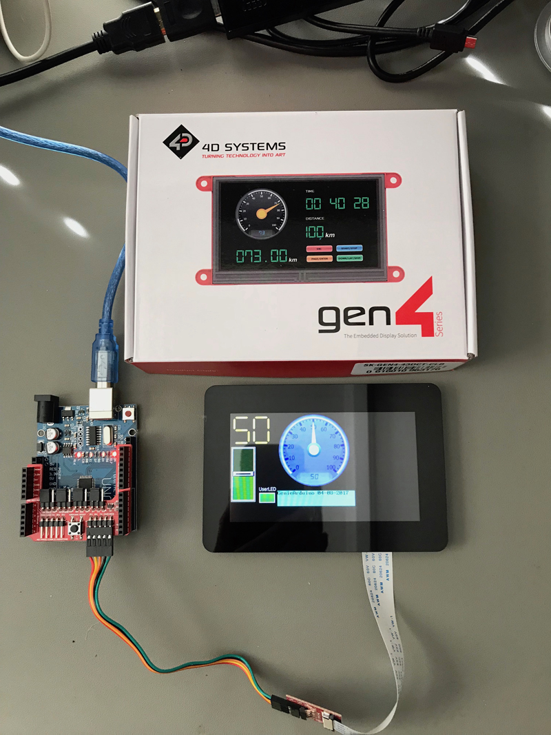
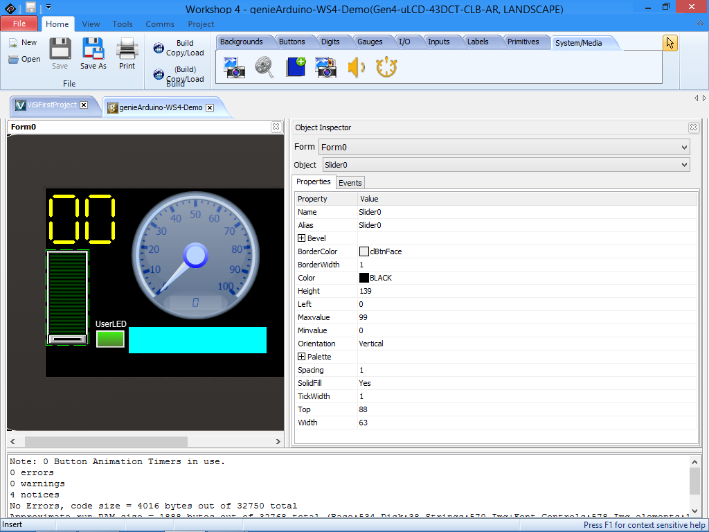
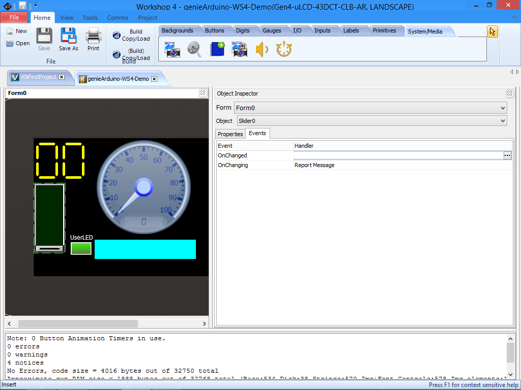
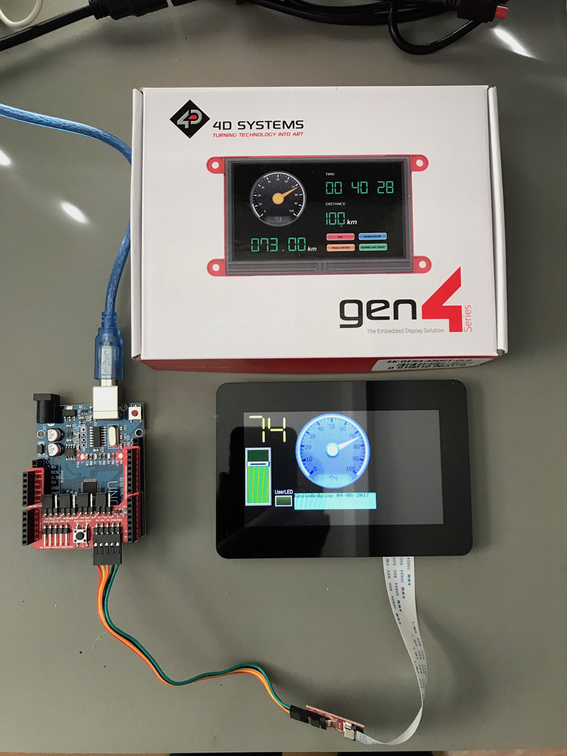
Figure 1 shows a typical application using a gen4-uLCD-43DCT-CLB display module, which features a 4.3in colour TFT LCD display with capacitive touch screen and cover lens bezel. When used with the 4D Arduino Adapter Shield II, the module can be easily connected to any Arduino-compatible board, allowing it to replace a range of electromechanical devices. In the example shown, the display features a simple slider and a gauge. The images in Figure 2 show how the slider is configured in the Workshop4 IDE; Figure 2a shows the slider’s general property which controls how it appears and behaves on the screen, while Figure 2b shows how the event behind the image can be set to update when the slider is moved and released or as the slider is moving.
Click image to enlarge
Figure 2a. Slider in Workshop4 IDE general property controls
Click image to enlarge
Figure 2b. Slider in Workshop4 IDE event update
The Arduino sketch snippet in Figure 3 shows how the slider is accessed by the host board. In this example the slider’s value is read from the display and used to update the gauge, showing how information is passed between the display and the host.

Click image to enlarge
Figure 3. Arduino sketch snippet
Compare the slider and gauge values in Figure 4 to those in Figure 1; it shows how the updated slider value is relayed to the gauge. This simple example encapsulates how easy it is to not only add a graphical interface to an Arduino, but how the display can become an integral part of the control functions. This example was achieved without the need for any programming in the Workshop4 IDE.
Click image to enlarge
Figure 4. Updated slider and gauge values
Speeding the design process
Engineers can approach the design in a number of ways. For software engineers, Designer is an environment for coding using 4DSystems’ propriety high level programming language, 4DGL. This provides a way of directly programming the graphics processor that powers the display modules, with a syntax that is similar to other high level languages.
For engineers that prefer to work in a visual way, Visi is a ‘Drag & Drop’ environment that allows graphical widgets such as switches, sliders and LEDs, as well as static or animated shapes (with layers) to be dragged on to a graphical representation of the screen being used, where they can be resized or otherwise modified. Using ViSi can significantly reduce the need for coding using 4DGL, but for an even more automated approach, ViSi-Genie provides complete code generation; no 4DGL coding is required at all. A fourth option is Serial mode, where the module simply acts as a slave display, allowing all of its functionality to be controlled by the host MCU or processor over a serial link.
Whatever design approach is used, the files generated are stored on the display module in ROM and a Micro SD Card; a socket is included in all display modules for this purpose.
4D Systems