Using reference designs to optimize selection of power-supply magnetics
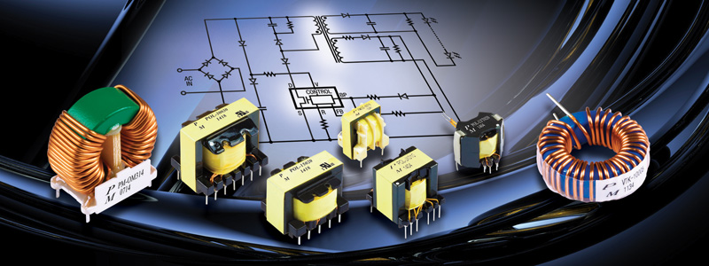
Figure 1. Proper selection and deployment of magnetic components provides cascading benefits across the board
A precision discipline that must apply engineering solutions in the real world, power supply design has always been a pursuit for the optimal solution. Analog engineering is not an a la carte design process -- every device in the circuit impacts the others around it, especially in the area of passives. One area of power supply design that remains complex and often challenging to many design engineers is the selection of the proper magnetic components.
Many engineers are faced with a choice between buying a solution that is well engineered and backed and supported by another, but may not be optimal to serve the application, or designing their own power solution that is optimized for the role but is not as cost-effective or fast to implement. This is especially critical when it comes to the selection of the magnetic components, as these devices offer many opportunities for system optimization, or if poorly implemented, a troubleshooting nightmare to find the inefficiencies and noise in a device.
Old solution, new light
Reference designs are an excellent solution to the problem, a “compromise” that does not require any real compromises. Long used in segments such as semiconductors, sensors, ICs, and microcontrollers, reference designs enable a manufacturer to highlight a new device by creating a tailored circuit to enable engineers to evaluate their device in a real-world application. A good reference design is only a build away from being a complete product, and has been evaluated and tested by the device manufacturer themselves.
Just as PMIC manufacturers have accelerated effective power supply design with reference designs, magnetic component producers are creating their own solutions by working with PMIC producers to create reference designs that yield optimal performance in terms of functionality, efficiency, and size. Advanced PMICs combined with advances in power switching devices (MOSFETs, GaN and SiC) are resulting in power conversion efficiencies simply unheard of even a few years ago.
Many reference designs are complete with schematics, printed circuit layout templates, SPICE models, and Gerber files. In exceptional (read “high volume”) circumstances, most manufacturers will provide a turn-key design integrated into the customer’s product. Generally, reference designs are nominal – providing a solution for a “typical” set of input/output characteristics. They may come close to what’s required. But as the old saying goes, “close only counts in horseshoes and hand grenades.” That’s why a reference design is often the ideal starting point when developing a power system, as it allows for further tweaking and optimization from a known design.
Taking the mystery out of magnetics
Analog power design is often considered an arcane practice in engineering as energy management is a brute-force application space dealing with real power in voltages and currents that can hurt people and damage equipment. Releasing the magic smoke in a catastrophic power system failure is the least of your worries in a problematic design. On the other hand, proper selection and deployment of magnetic components can allow an engineer to achieve higher power densities, lower profile aspect ratio, gain higher system efficiencies, and improve thermal performance, with cascading benefits across the board (Figure 1).
One cannot underemphasize the importance of the impact of magnetic design on power converter performance, and providing an overview of the trade-offs in the application of various magnetic materials is one advantage in using a reference design as a starting point for your design process.
Transformers must be properly designed to achieve acceptable power coupling, tight voltage regulation with low loss and distortion, as well as carry the expected values of primary and secondary winding current without any trouble. The perfect transformer would have no leakage inductance, exact voltage regulation, no hysteresis or eddy current losses, and be able to handle any amount of current. Sadly, this would result in a device insanely large and heavy, which is why compromises must be made.
Issues in developing power magnetics range from developing materials and geometries for high-frequency systems to the integration of magnetics in point-of-load converters and other chipscale devices. This includes addressing AC power loss in conductors and magnetic materials, with important relevant technical issues such as ac power loss, core loss modeling and simulation, near magnetic field characterization, thermal constraints, inductance characterization, and modeling. In addition, there is pressure on power magnetics to support emerging electronic power circuit topologies.
The Magnetics Seminars and Industry Sessions at APEC have been among the most popular over the past two years, but they just reinforce the “mystery” surrounding magnetics design. Analog design expert Ray Ridley recently pointed out that designers shouldn’t expect any breakthroughs in magnetics technology. He also said we don’t need any. We just need to properly design what we already have.
Designing magnetics for switching power supplies
Transformer design requires consideration of several factors: primary turns count, secondary turns count, wire size, inductance, air gap, core material, and physical size. There is, of course, also power lost due to resistance of the wire windings, dissipated in the form of heat through the conductors into the board and heatsink (if present). Increasing the gauge of the winding wire is one way to minimize this loss, but only with substantial increases in cost, size, and weight.
The bulk of transformer power loss is due to magnetic effects in the core, the most significant of these being eddy-current loss, which is resistive power dissipation due to the passage of induced currents through the core. With an iron core, there will be currents induced in it just as there are currents induced in the secondary windings from the alternating magnetic field. These induced currents circulate through the core perpendicularly to the primary winding turns, giving them their novel name, as they behave a bit like eddies in flowing water.
An inductor is a coil wrapped around a magnetic material to induce a magnetic flux concentrated in the core for energy storage or high-frequency filtering. In an inductor, you can use the same core but with different lengths of wire to get the different inductances. The DC resistance of the inductor is basically determined by the length of the wire that's used in wrapping the inductor. Issues here involve parasitic capacitance in the wrapping of the inductor. This resistance must be as low as possible as it affects system efficiency and the ability to work at higher currents.
In addition, there is AC resistance, an accumulation of several different effects, from skin effect to losses in the core material itself, from hysteresis and/or eddy current. The magnetic field itself will induce a current in the magnetic material and that current will dissipate energy. The self-resonant frequency is the frequency at which your inductor is no longer useful. Also, as you increase the current, you get a lower inductance, and as that flux density reaches a certain limit, the flux will no longer be able to travel through the core material (and you will lose inductance). If you have a power supply where the inductor saturates, that can cause the ripple current to run out of control, damaging downstream components.
There are also different core materials, ferrite and iron powder cores. A ferrite core has better high frequency efficiency, but also a steep saturation curve. The advantage of an iron powder core is it doesn’t have that steep saturation curve, an advantage when you don't know how much current you're going to be using. Iron powder very unlikely to saturate in a way that causes destruction of downstream components. However, it's not very good for higher frequency designs.
Start with a reference design
Ultimately, the final design of a power system requires a bit of tuning, and that can often mean making changes to the magnetics, that’s why magnetics suppliers can be the best resource for power supply reference designs. PMIC-based power conversion circuit reference designs require close collaboration between the PMIC vendor and the magnetics manufacturer, as the designs are often device-specific and are typically designed for specific power requirements. (Figure 2).
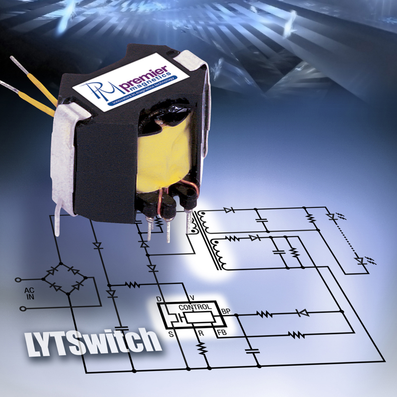
Click image to enlarge
Figure 2. An example of a reference design for a Power Integrations PMIC utilizing magnetics from Premier Magnetics
Reference designs are a great tool that can speed the implementation of power conversion circuits utilizing power management ICs and the associated power semiconductors, diodes, resistors, capacitors, inductors and transformers. The design can also be more easily modified, as you are working from a functional design and only changing some variables in topology or component choice as opposed to creating a circuit out of whole cloth, troubleshooting and streamlining it, then modifying it for different application spaces.
The magnetic components require a great deal of care in their selection. Magnetics suppliers like Premier Magnetics work closely with PMIC suppliers to produce functional and adaptable designs. But it doesn’t end there. Actual circuit demands often require adjustments in these designs and firms like Premier Magnetics can provide the expertise to speed the design to a successful implementation.
Premier Magnetics