Adhesion Control Protects Inspection Robot Investment
3DHALL sensors make climbing inspection robots smarter and safer
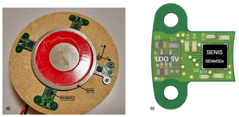
Figure 1: a) Gripper foot prototype in bottom view with four equally distanced SENM3Dx sensors on PCBs and the electro permanent magnet (EPM). The magnetic axis definition is shown for one sensor. b) Sensor PCB bottom view with SENIS SENM3Dx
Robotic solutions are well recognized for their potential in the field of inspection and maintenance, especially for ferrous (steel) structures, such as complex bridge structures and towers. In practice, this means that industrial climbing robots equipped with electro permanent magnet (EPM) grippers are used whenever safety concerns for human inspectors are predicted. Efficiency and accuracy of inspection can be improved, costs can be reduced, and new techniques can be introduced. Usually, these robots are relatively heavy and expensive, and therefore to reduce the likelihood of it falling, accurate information about the actual (magnetic) adhesive force or grip of the EPM to the support structure is necessary. These details also allow for energy-saving techniques to be employed during climbing and to ensure the robot avoids areas that provide too little support.
The proposed method of estimating magnetic adhesive force is based on the SENIS SENM3Dx 3D-magnetic field sensors which are placed on the edge of a gripper foot probing the fringe field of the EPM. An adhesive force model was developed and a prototype was built using the EPM VM65/ND manufactured by NAFSA and four SENM3Dx sensors (Fig.1 a) and b)). The optimal sensor position was derived from electro-magnetic (EM) simulations showing the location of maximum magnetic field changes, which turned out to be adjacent to the gripper foot housing.
Adhesive force depends on many real-world parameters, however, only four were selected for the model: strength of the permanent magnet, air gap between the EPM and support, support (metal) thickness, and support surface texture. Note that the magnetic properties of the support (i.e., relative permeability) are not considered since the material is assumed to be saturated and thus the adhesion force is proportional to the thickness. Furthermore, four sensors allow the collecting of information on the foot orientation with respect to the support surface.
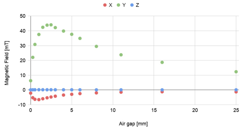
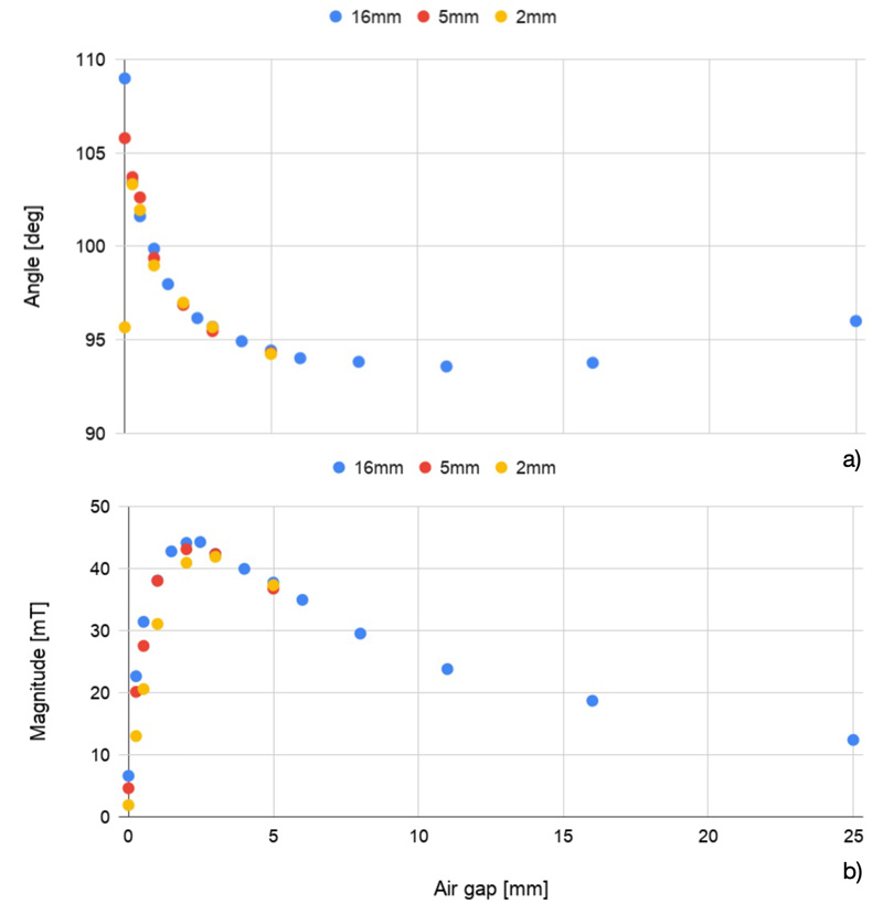
Initial magnetic flux measurements for different air gap distances show, as expected, that the Z-component (tangential) of the magnetic field at the sensor location is almost zero and thus does not provide information (see Fig. 2). Therefore, it is convenient and intuitive to define an angle between the X and Y component,which provides information about the air gap up to a certain distance, since large air gaps lead to an angle of ideally 90° (Fig. 3a). Note that for reasonably thick supports structures, the angle does not depend on its thickness. Figure 3a also shows that for diminishing air gaps, the relative error in the magnetic field component measurements dominates and may produce outliers.
Click image to enlarge
Figure 2: Magnetic field components measured for different air gaps with a 16 mm thick steel plate as support
The magnetic field amplitude or magnitude M calculated by the X and Y component, provides information about the adhesion force (Fig. 3b) since there is an almost linear dependence for relatively small air gaps. Since the magnetic angle provides less robust data for the adhesion force compared to the magnetic magnitude, the latter was not used to build asimple, linear prediction model. In other words, the air gap distance can be estimated by the magnetic angle and the adhesion force by the magnetic field magnitude, based on the fact that the adhesion force is approximately proportional to the magnetic field magnitude for a given air gap.
Click image to enlarge
Figure 3 a:) Magnetic angle for different air gaps. b) Magnetic field magnitude M for different air gaps. A 16 mm thick steel plate was used as support
The model is shown in the equation below and it predicts the adhesion force using the data of a 5 mm thick steel plate based on the magnetic magnitude and an independent force measurement from the 16 mm and 2 mm metal plate. The equation shows the model which is expressed as a function of the air gap width (d), where the subscript indicates the thickness of the metal support. Thus, the model F5,pred(d) predicts the adhesion force for a 5 mm thick metal plate using the magnetic magnitude (M) and force measurements (F) of 2, 5 and 16 mm thick metal supports.

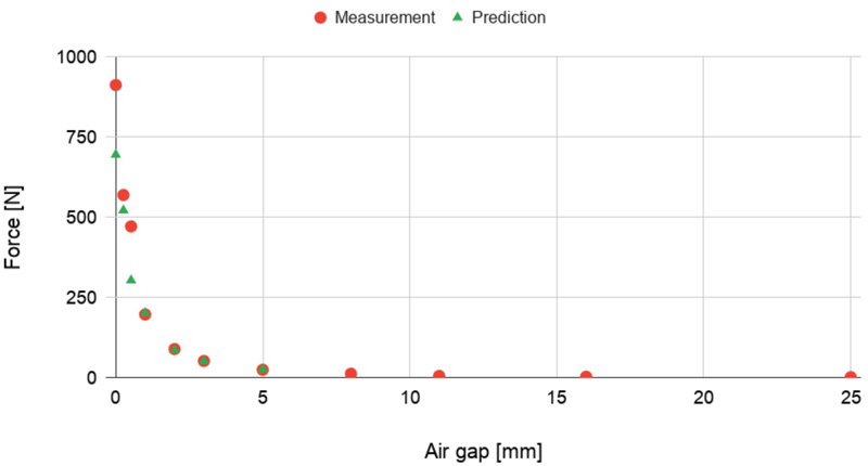
Fig. 4 shows the comparison of predicted and measured adhesion force values as a function of the air gap distance d, with a relative maximum error of 23%. This model performance appears to be already sufficiently accurate, since the magnet is chosen with a stronger adhesion force which is necessary for safety reasons. This safety margin allows the use of the model in real-world applications without further optimization. Furthermore, the fast, dynamic responses of the SENM3Dx sensor allows the use of adaptive models that can train models and react in real-time. It is also very convenient to be able to infer the adhesion force from a small, light-weight 3D magnetic field sensor.
Click image to enlarge
Figure 4: Performance of the linear prediction model F5,pred Comparison of model (Prediction) to measured adhesion force (Measurement) for various air gaps d
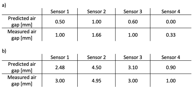
Finally, since the model can be used in an inverse manner, the data of each of the four magnetic field sensors leads to an estimate of the actual air gap which gives information about the gripper foot orientation. The table below summarizes the inferred air gaps from the 3D magnetic field sensor data for two air gaps. Even though the data is not corrected and shows small air gaps with relatively high deviations, it is clearly a useful tool to estimate the gripper foot orientation. With improved models and/or sensor data calibration, results will improve significantly.
Click image to enlarge
Table 1: Inferred air gap from 3D magnetic field data for the insertion of a 1 mm a) and a 3 mm step spacer
Conclusions and Outlook
In order to determine the gap accurately, and therefore to optimize the control of magnetic grippers, it is important to measure both the direction and the strength of the total magnetic field. This can only be done by measuring accurately all three components of the magnetic field at the same time and at the same location, i.e. in one small spot. SENIS 3D Hall sensors measure these components in a very small field sensitive volume of 100 x 100 x 10 μm2 and in 3 directions with a resolution of 10 µT. 1D or 2D sensors are not sufficient for this task and low field sensors, such as GMR sensors are not suitable due to the high dynamic range required.
The smaller the field sensitive volume of a 3D sensor is, the better it can provide reliable measurements in applications that involve high field gradients as presented in this work. SENIS is steadily improving the performance of its measurement solutions and moving the limits of what is feasible now in the field of magnetometry and sensor technology.


