Electrical motors are becoming even more important to the automotive industry for applications that previously relied on switches and relays.
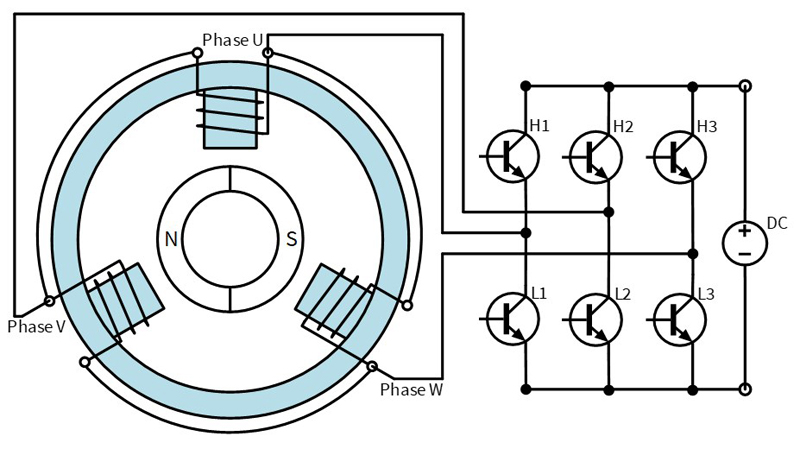
Figure 1: Principle of BLDC- and PMSM-motor with a B6 Bridge
In the past, the number of automotive applications driven by electrical motors increased from year to year. In the beginning, there were only a few applications such as brushed DC-motors, fuel pumps, windshield wipers, ABS, or window lifters, that were simply controlled by switches or relays. For these electrically driven applications new solutions were required to control the speed, position, or torque of the motor to improve efficiency, performance, and usability. Inverter-controlled synchronous motors with high speed, position, or torque control were mainly used in high-performance applications where expensive and large inverters were not the main cost limit.
The performance and functionality of modern controllers offers the possibility of measuring electrical parameters during motor operation and calculating the needed rotor position for correct commutation. This replaces the sensors previously required, improving reliability, and optimizing the cost of the system. Different commutation behaviors can also be implemented, for instance field weakening, and start/stop ramps. In addition, new applications have been developed, where fast and exact torque, speed or position control is necessary, such as automatic gear shifting, double clutch systems, and field weakening.
With the ongoing development of control algorithm, the customers are defining new, demanding requirements. Two of these requirements are the acoustic noise emission in high-quality applications and the current ripple quality inside the electrical system. The only way to meet these requirements is through sinusoidal energy conversation. However, to keep investment costs low, customers often simply adapt existing designs to new tasks. This can lead to difficulties that cannot be solved. In this case, an analysis of the magnetic system should be carried out to investigate the physical limits of the motor and its characteristics.
To simplify the development of the internal software algorithm for commutating the motor, MOTEON has created a permanent magnet synchronous motor (PMSM) as a reference design with an ideal sinusoidal induced voltage shape (Back-EMF) and derived two inductance variants: one design with salient inductance difference between d- and q-axis (salient), the second design with almost constant inductance between d- and q-axis (non-salient). With these setups, the investigation of additional reluctance torque and reluctance-free torque is supported and can be tested.
Motor Operating Principles
Electrical motors operate using various functional principles, which are based on one of two physical effects: reluctance, Lorentz, or a combination of both. With advances in the research of permanent magnet materials, it is becoming increasingly affordable to use permanent magnet materials in medium and low power applications below 1000 W. With the strength of permanent magnet materials, the torque density of electrical motors can be significant increased, which is ideal for automotive applications with limited space. In turn, strong permanent magnetic materials can be used in weaker but very cost-effective plastic-bonded and molded materials.
A major advantage of permanent-magnetic rotors is the absence of an electrical connection; only a bearing is required as a mechanical support. It is also possible to have separation between the electrical part, the stator and electronics, and the mechanical part, the rotor, without the need for a seal.
The stator coils are connected to the electronics that control the electric power distribution to the coils. As a result, the brushed DC-motor was initially replaced by block commutated permanent magnetic motors. These are commonly known as BLDC (brushless direct current motor). For a sinusoidal commutation, a sinusoidal motor characteristic is necessary, which is defined by the motor design. The rotor follows the rotating stator field in a synchronous manner, which is why this motor principle is called “permanent magnet synchronous motor” (PMSM)
Topology of a PMSM
The typical motor topology of a PMSM consists of a multiple of three phases in the stator and a multiple of two magnetic poles in the rotor. But only a few of these combinations are useful for a rotating motor with good torque. The shape of the induced voltage, which is relevant for working with commutation electronics, is determined by the ratio of the sizes of stator poles to the rotor pole. Some combinations produce a more trapezoidal induced voltage, others a more sinusoidal voltage.
The induced voltage also depends on the coil arrangement. With coils distributed over several teeth, a sinusoidal voltage shape can be optimized. However, this additional effort is only required for large and powerful motors. For cost-sensitive reasons, concentrated coils, in other words one coil per tooth, are preferred.
The placement of the magnets on the surface or integrated in the rotor also determines the shape of the induced voltage. The decision for an internal or external runner motor is mainly influenced by the application.
Finite Element Design
By using the finite element method (ANSYS Maxwell), new magnet designs for BLDC/PMSM motors can be developed, or existing motors re-engineered. In the design process, a suitable design for the ferromagnetic stator (yoke, tooth, tooth-pole), air gap, coil window, magnets and ferromagnetic rotor can be investigated. The design is mainly influenced by customer requirements for the air gap, torque, speed, or design space (length, diameter). Different requirements lead to different optimized topologies.
The first goal is the implementation of an ideally high pole number, providing high commutation frequency. A high commutation frequency means high torque density, less material consumption and effective utilization of the resources. At the same time, negative influences such as magnetic flux leakage and mechanical production limits increase as the system structure becomes smaller. The design process evaluates the best solution for the desired application.
The path to the best solution is not determined by the magnetic domain alone. Customer products are highly integrated mechatronic devices. The optimal design process is reached by incorporating the mechanical, magnetic, and electronic domain in one design process – in other words, in a mechatronic approach.
PMSM reference design
The MOTEON PMSM is designed for an electrical input power of 100 W. The design target was an ideal sinusoidal induced voltage shape: one motor with salient and one with non-salient characteristics. The motors were calculated for a nominal torque of 0.22 Nm at 3600 rpm with a mechanical power of around 80 W. This set-up is common for water and oil pumps in automotive applications. To support algorithm development, the motor is used with its salient and non-salient characteristics.
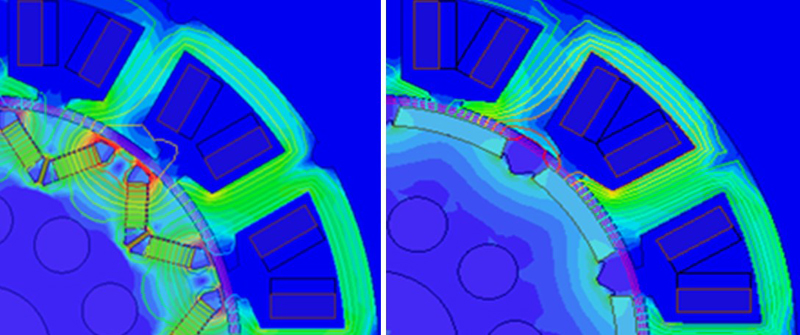
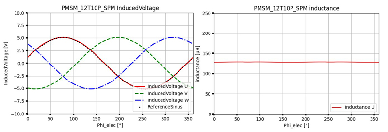
The motors feature a topology with 12 slots and 10 poles. The salient inductance characteristic (Ld ≠ Lq) is achieved by a V-shaped arrangement of the magnets within the rotor-lamina (integrated permanent magnets; IPM) (Fig. 2). This creates magnetic conducting paths with different resistances in the d- and q-axis of the rotor (salient pole). The FEM design for the salient rotor is optimized in detail with regard to an ideally sinusoidal inductance characteristic (Fig. 3).
Click image to enlarge
Figure 2: Magnetic flux density of V-shape (IPM) with salient inductance (left) and surface magnets (SPM) with non-salient inductance (right)

Click image to enlarge
Figure 3: Induced voltage shape (left) and inductance shape (right) of the salient motor design
In the second example, a rotor design with non-salient characteristics is desired. For this design, the same stator design is used. The non-salient characteristic is achieved using surface-mounted magnets (SPM), in which the inductance in d- and q-axis is nearly constant (Ld = Lq).
Click image to enlarge
Figure 4: Induced voltage shape (left) and inductance shape(right) of the non-salient motor design
This design offers a stronger connection between rotor and stator with fewer short-circuit paths. For this reason, a weaker magnet material is used to reach the same value of permanent magnetic flux. In this case, a plastic-bonded neodymium material is chosen.
Motor data and characteristics
The motors are prototyped in-house. The different parts, such as lamina, magnets, and plastic parts, are fabricated by external suppliers. After assembling and functional tests, the motors are measured, with the differences between FEM design and physical measurement particularly interesting for the design process (Table 1). Possible deviations are mainly caused by the sum of tolerances and deviations in geometries and material properties.
The salient motor with IPMs has a weaker permanent magnetic flux than expected (-16 percent). The reason for this may be greater magnetic short-circuit fluxes in the surrounding windows of the magnets than were expected in the FEM design. The spokes of the windows are very small, mechanical tolerances in the width of the spokes have a direct effect on the amount of short-circuit flux. The loss could possibly be compensated for with a slightly stronger magnet material. In contrast, the inductance values are close to the FEM design (-8 percent).
The non-salient motor with SPMs comes very close to the FEM design values, in particular the permanent magnetic flux is very close (-0.4 percent). There is a small deviation in the inductance between q- and d-axis, which results in negligible reluctance behavior (minimal salient).
The difference of the ohmic strand resistance differs depending on the wire length. The resistances are higher than expected, which means that more copper wire used.

Click image to enlarge
Table 1: Results of the motor data
The MOTEON Motor Analysis Tool tested the motor parameters quickly, and the motor characteristics can be displayed at 12 V supply voltage. The salient motor shows a clear reluctance-torque characteristic, while the non-salient motor shows only a small reluctance-torque characteristic, which is due to the deviation in axis inductance. Due to the lower value of the permanent magnetic flux, the speed of the salient motor is faster, while the torque level is slightly lower.


