The risk-free route to power system designs
High performance power systems have now progressed to the point where designers are working with multiple input voltages, driving multiple rails for a wide variety of applications. With a need to ensure that the PoL regulators are located as close to the load as possible, designers need to pack a lot of power conversion into a very small area. At the same time, company resources are becoming stretched to the point where engineers are expected to multi-task, with generalists rather than power specialists frequently being responsible for designing the power system. Today’s complex power requirements, therefore, can present the designer with quite a headache: how to deliver high performance power with diverse sources to a diverse set of loads, ensuring that all parts of the architecture are operating within their power and thermal limits, while also optimizing efficiency and cost targets.
New applications present further challenges. For example, as part of the move to cheaper, cleaner and more efficient energy generation and usage driven by governments, organizations are looking at how they can meet legislative and cost objectives by moving to High Voltage DC (HVDC) power distribution. Which requires a different approach to power system design for the electronic equipment being used.
In this article we look at the issues, technology, methodology, tools and building blocks that can be used to get even a complex power system project through to successful completion.
Old ways have been overtaken by system demands
Looking back 30 years, most systems’ power requirements were served by a centralized power supply. Electronics technology, however, was on a trend that required devices that were smaller, lighter and yet more powerful. Communications equipment was developed to enable an internet revolution, which required data centers filled with servers. Systems became smaller, offered higher performance, and became more demanding in their power requirements.
It became evident that something else needed to evolve as well – the way electronic devices were being powered. Large centralized power supplies were simply not up to the task of powering next-generation products, and therefore power conversion needed to move closer to the load. Gone were the days of being able to power equipment with centralized boxes.
Power conversion needed to address the varied requirements of new loads: one voltage couldn’t fit all. Loads now require multiple voltage rails, need to meet tight regulation requirements, and need fast transient response. As a result power conversion had to become an integral part of the system, which needs to be designed inside, and alongside, the equipment.
We’ve seen the trend of heat dissipation density rising over time as devices have been driven smaller by the need to be located closer to the point of load. The drive to make smaller power components has outstripped commensurate improvements in efficiency. Devices such as bricks, which formed the backbone of power systems for many years, are becoming power-density limited. It should be clear that in addition to being more efficient, power components also need to be more thermally adept and support flexible thermal management.
New power components enable new approaches
Power density cannot continue to rise without fundamental advances in packaging technology. New power components that can be used as the building blocks of modern systems are being developed that offer higher power density, better thermal performance, larger voltage step-down ratios and integrated magnetic structures. These components are also enabling the emergence of the new power distribution designs, including Factorized Power Architecture (FPA), and supporting new applications such as High Voltage DC (HVDC), which enable further improvements in efficiency, and the use of alternative energy.
So how does the engineer propelled into the position of being responsible for designing an optimized power supply system in a project get to grips with architecting a design that makes full use of the high performance building blocks now available? This is indeed a tough call – especially if this is not your field of expertise. What is needed here is a risk-free methodology with plenty of support along the way. Getting it wrong is simply not an option; re-spins are expensive and can result in the window of opportunity being missed.
Vicor, a company right at the front line of power design innovation has pioneered the power component design methodology. Engineers can configure high performance power systems predictably and cost-effectively from a proven methodology, using industry-proven components. .
Power components are specialized blocks that are fully optimized by expert power engineers for efficiency, power density, transient response and EMI. By taking this approach, rather than developing power chains using discrete components, all these key parameters are already optimized and ready for the designer to use for a best-fit solution for any power design project. Additionally, the configuration of these blocks is completely re-useable for future designs, saving time and effort.
When coupled with the range of tools and resources that are available, this method will provide a faster and easier design cycle with lower risk to complete the project and get to market.
There are three steps in the power component design methodology: identify, architect and implement.
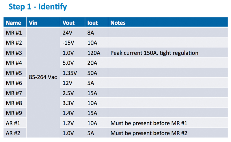
Step 1 - Identify
This is the “big picture” view of a project’s power requirement, defining the number of rails, voltages and current needs, as well as looking at the timing of the project. It is at this stage that a list of these needs is made and an initial consideration is given to the type of products that are available to meet these requirements.
Clcik image to enlarge
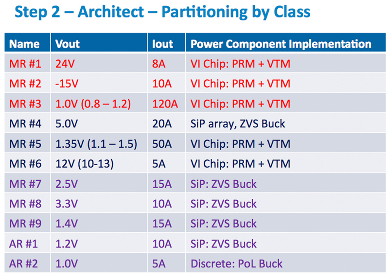
Figure 1: The first step is in listing the project power needs. In our example here we have assumed 11 rails and listed them in descending power levels. We have called these main rails (MR) and auxiliary rails (AR) for convenience. The notes column contains any special requirements
What kind of products can meet the requirements?. There are many sources for this information. For example, Vicor provides a solution selector tool that searches the database of components available and recommends solutions that meet the customer’s input and output needs. Using an intelligent tool such as the Vicor Solution Selector reduces the time to produce a shortlist of possible components to almost zero, and make it easy to select the best one for a particular design based upon the criteria that are most important to the application. Most engineers just do not have the luxury of “study time” to complete this important task manually.
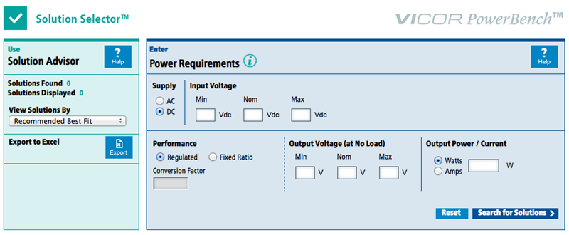
Click image to enlarge
Figure 2: Use Vicor’s PowerBench tool to simplify the component selection process
What’s available – typical power components:
First there is power delivery. Here power components are required to take a high voltage DC or AC source and bring it to a Safety Extra-Low Voltage (SELV). In many high performance applications engineers are working with high voltages and high current to deliver power to their system. Given the heat dissipating from the devices, choosing components that are thermally adept is critical. These components will need to be placed in a number of locations inside the system. This includes mounting the power system on a chassis or on the motherboard, and the appropriate cooling for each will need to be considered.
Next is delivering power from SELV to the point of load. Engineers need to be careful in the selection of the proper rail for their application. Having too many stages in conversion will reduce efficiency in the application. In recent years power designs have started to move from a 12V rail to a 48V rail to deliver higher efficiency systems. The challenge is selecting the best components that deliver the proper performance at the highest efficiency. Tools like Vicor’s Whiteboard help engineers evaluate the performance using different SELVs for their design.
Finally there is the selection of the point of load components. Based on the SELV selected the engineer needs to pick the components required to reach the PoL requirements, which can go to sub 1v at high current. Where isolation and regulation is required, DC-DC converters, such as the Vicor DC Converter Module (DCM) can be used. Designers can also make use of components designed for Factorized Power Architectures, where the regulation and voltage transformation / isolation functions are separated. Choosing the latter enables the designer to have high power density, which translates to the ability to convert a lot of power in a small space.
Step 2 – Architect
The first step in architecting the system is to create a block diagram of the power system, starting at the output and then working backwards towards the input. It works better to start at the lowest power level, and work up from there, so that the power component class can be reviewed and changed wherever necessary as the power level grows.
It is important to select the right component class for the appropriate power level. For example, at low power, System in Package products (SiPs) such as Vicor ZVS Buck Regulators is the best solution. At higher power levels a better approach might be to use Vicor’s ChiP products (Converter housed in Package). Depending on the complexity of the number of rails required to drive the loads a mixture of SiPs and ChiPs may be used in the application.
This will aid the achievement of maximum power density and cost effectiveness within the system, and maintain high efficiency operation of every device in the system.
Looking back at Figure 1, it is clear that the first three rails (MR#1, 2 and 3) are the rails that require the highest power class devices, while the last five (MR#7 through AR#2) are lowest in power class. The remainder (MR#4 through MR#6) are somewhere in between. The designer would need to use their discretion and judgment in terms of device selection here. Working back from the outputs, it is possible to start to build up a picture in the system block diagram of the classes and power levels of the power blocks that we need.
Click image to enlarge
 Figure 3: From the analysis of the power rail requirements, we can determine the most appropriate power component class

Click image to enlarge
Figure 4a:
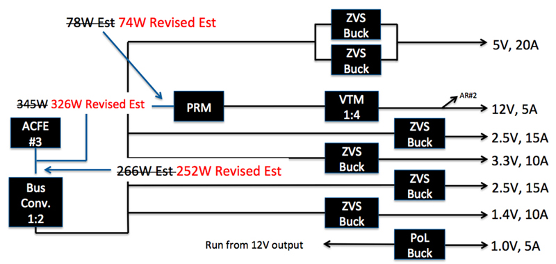
Click image to enlarge
Figure 4b:
Figure 4a & b: Continuing to work back we can identify the classes of components necessary to deliver the power levels in each rail. At this stage we should always bear in mind the power levels required to ensure we balance the loads and utilize the power capacity of each individual device. Here we see the refinement of our original estimations
Click image to enlarge
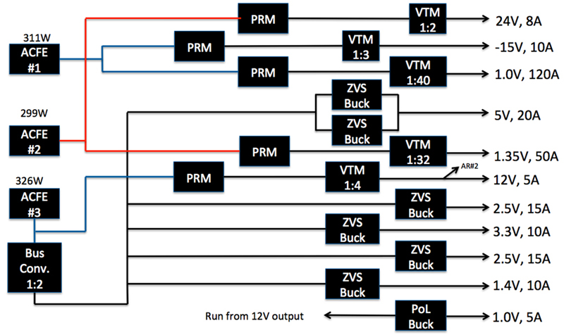
Figure 5: Here we see the ACFEs are now brought in to drive the rails. It is important here to judge the loads on each and to ensure the loads are spread to operate at near maximum with a suitable safety margin.
Step 3 – Implement
Once the blocks have been finalized, the designer needs to match part numbers to these blocks, as well as noting any special circuits for implementing functions and simulate individual chains of power conversion components. Additional circuitry that needs to be developed might include filters, holdup circuitry and power sequencing. The engineer should also think about thermal, termination, and packaging considerations at this stage of the design.
In our example, there are some special requirements for the power supply: a delay on MR #3 until auxiliary rails are up; and tight regulation on MR #3, which will require the use of a remote sense loop. It would also make sense to consider configuring the PRMs for the exact load current limit and other parameters to match exactly the rail and load requirements.
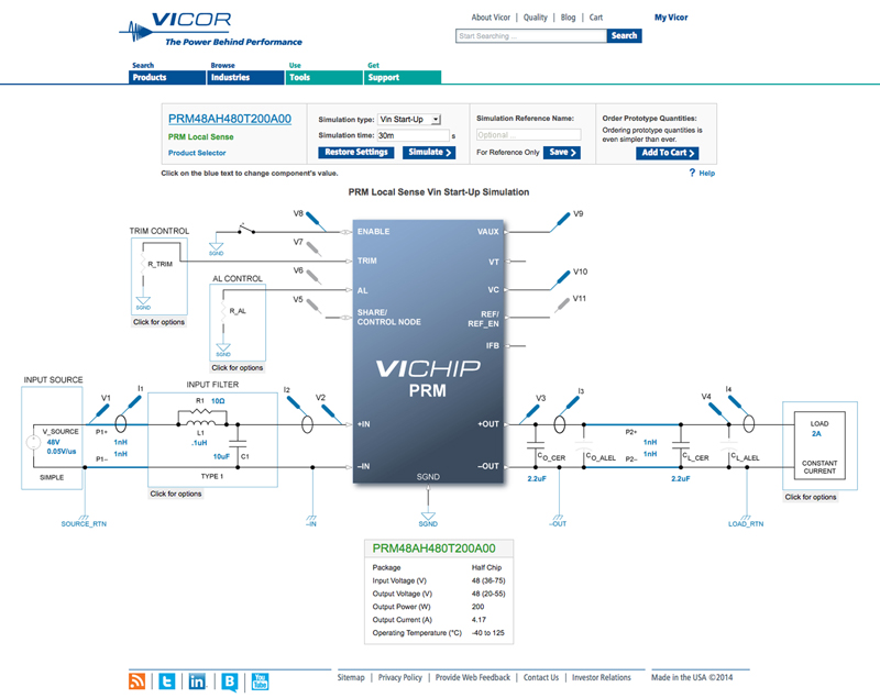
For engineers who need to tweak the design using the PRM, Vicor provides a PowerBench simulator that assists further understanding of the performance of the system.
Clck image to enlarge
Figure 6: The PowerBench PRM Simulator.
Design and development tools
In the past, engineers have made component selection and analyzed the power system efficiency of each stage (and of the total system performance) by calculations that reference the device datasheets.

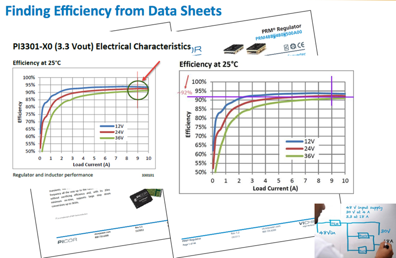
Click image to enlarge
Figure 7: Obtaining performance information can be time consuming and laborious
Although completely satisfactory, this method can become more than a little tedious. In order to streamline the design process and save time, Vicor recently introduced the PowerBench Whiteboard. The Whiteboard is an online tool to design and analyze power systems with the appropriate set of Vicor power conversion components. With The Whiteboard it is no longer necessary to wade through the operating and efficiency parameters contained in the datasheets, instead an engineer simply draws the blocks in the online tool and all calculations are done within milliseconds.
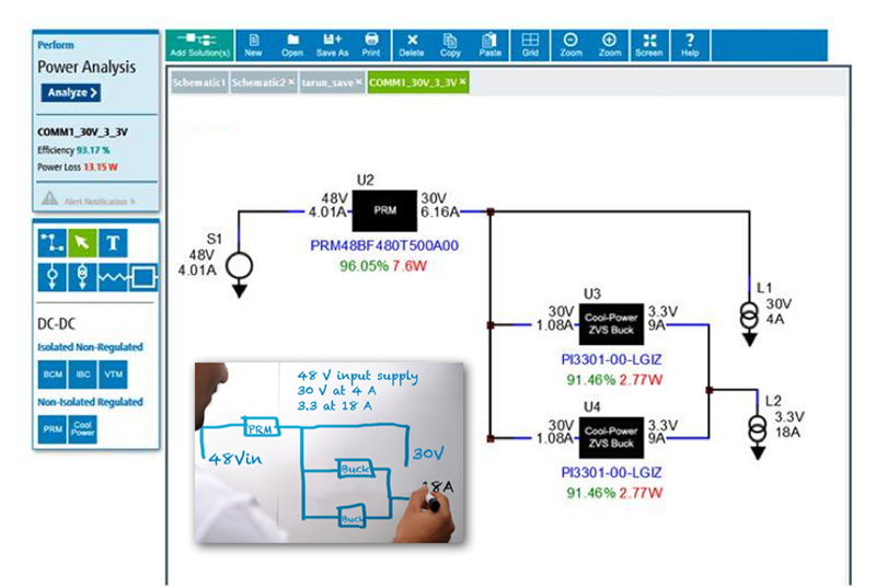
Clcik image to enlarge

Figure 8: Whiteboard saves time and effort by automatically analyzing the design and delivering performance data in milliseconds
By keeping the familiar metaphor of sketching a system on a whiteboard, but adding automatic parameter lookup and calculation, the Whiteboard further reduces the time to complete a design when using the power component design methodology.
In addition, Vicor’s Solution Selector is tightly coupled to the Whiteboard tool. So a design recommended by the solution selector can automatically import the design into the Whiteboard so that the engineer does not need to draw the system themselves. At this point, the engineer can tweak the design to further meet their needs and quickly understand the efficiency of the design.
Conclusion
Power components have been a key factor in allowing engineers to design the complex, high performance power systems for today’s electronic systems. As they have been optimized for efficiency, power density, transient response, EMI and cost effectiveness by power design experts, almost any electronics engineer can develop a power system that meets challenging high performance requirements by leveraging these devices.
Many of the recent power component innovations have been driven by the requirement for better thermal performance. The ChiP platform, which provides a thermally-adept solution using two-sided cooling, is a good example for on-board power. In the future, other innovations will further simplify the task of power system designers, particularly at the front end of the power supply.
This article has shown that power component design methodology provides a simple three-step approach that allows engineers, even non-power specialists, to construct complex power chains that deliver high efficiency and power density. This approach is further simplified by the use of online tools. Unlike many design approaches, however, the power component design methodology removes the pain and risk from the design process without the need for engineers to spend time learning the technique. Engineers can use the methodology without special training to reduced development timescales, while ensuring that their next power chain is optimized to deliver the required performance.