Supercapacitors extend battery life
Figure 1
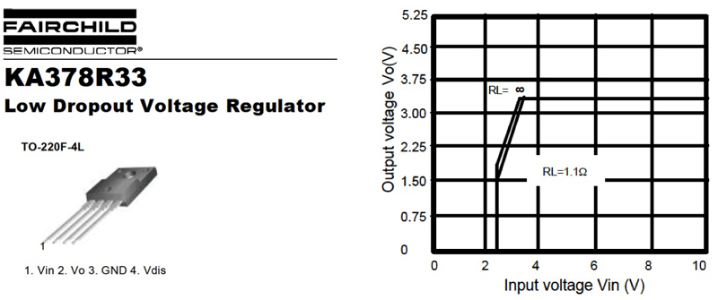
Supercapacitors, or Electrochemical Double Layer Capacitors (EDLCs), were invented in the 1960's and introduced for use in back-up applications by NEC in 1979 for clocks in VCRs, radios and microwave ovens. These EDLCs had high equivalent series resistance (ESR) values from tens to hundreds of ohms and were used in applications where the current requirements were in the ?A range. However, they were not suitable for pulse current applications where amps of current are required. A new class of low ESR (20 to 500m?) EDLCs was developed and brought to market by several companies in the late 1990s, and the use of these devices (e.g. BestCap® by AVX) is increasing rapidly for a variety of portable applications including cameras, bar-code scanners, medical devices, and smart metering. In these applications, the EDLC typically serves as a "battery chatter" countermeasure and/or in a "battery assist" function. This paper describes how an EDLC in the "battery assist" function can extend battery life, which is especially important for today's "power and energy" hungry electronic applications. Battery assist For current pulses of sufficiently short duration, a capacitor in a battery assist function effectively reduces the overall ESR of the power supply. For example, if the battery and capacitor have identical ESR, e.g. ESRcap = ESRbatt, then the ESR of the battery-capacitor power supply will be 1/2 ESRbatt. Reducing the overall power supply ESR has two implications. First, lower ESR reduces the Joule loss in the power supply. Second, lower ESR reduces the voltage drop during current pulses. The effect of reduced Joule loss in the power supply will be the topic of a future paper. The focus of this paper is the reduction of voltage drop during the current pulse, and the resulting extension of time to reach the "circuit cutoff voltage", or the voltage below which the circuit ceases to function correctly. To demonstrate the battery assist concept, a Li-ion battery, with and without a supercapacitor in parallel, will be discharged under a continuous GSM current pulse, and the time until "violation of cutoff voltage" will be measured. Cutoff voltage The term "cutoff voltage" is often used to refer to an IC's minimum power supply voltage. Microcontrollers are especially sensitive, as even a microsecond-order drop below the cutoff voltage can cause a reset. Power supply ICs, such as regulators, also have a specified minimum input voltage. The power supply IC will operate below this voltage, but at reduced output voltage. Though power supply ICs are not as sensitive as microcontrollers, the specification minimum input voltage should be maintained as a matter of good design practice. As an example, figure 1 shows the input-output characteristics of a 3.3V LDO from Fairchild Semiconductor. The graph shows that output voltage drops rapidly below 3.8V. Thus, a drop in regulator input voltage below its specification minimum could lead to a drop in the output voltage below the cutoff voltage of the IC to which it is supplying power.
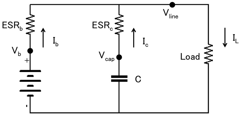
Voltage drop on current pulse Figure 2 shows the diagram of the battery assist application. When the load draws current, the line voltage drops is a combination of the voltage drop due to ESR and the voltage drop due to the discharge of the battery and the capacitor. The line voltage, battery current and capacitor current for a single pulse can be expressed as a function of time as follows. Inductance is ignored because it is very small in typical battery assist applications. C: Capacitance ESRb: Battery + connector ESR ESRc: Capacitor ESR Ib: Battery current ic: Capacitor current iL: Load current Vb: Battery voltage Vline: Line voltage
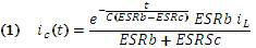

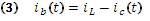
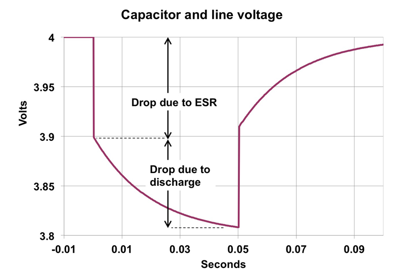
Figure 3 shows a generic plot of equation 2 for line voltage (the recharging portion of the curve is handled by a separate set of equations). The voltage drop of figure 3 can be separated into two parts: 1) voltage drop due to ESR, and 2) voltage drop due to capacitive discharge. The expression "sufficiently short duration" in the opening paragraph of the section "Battery assist" means a duration for which the contribution of capacitive discharge is small relative to that of ESR. The smaller the capacitance, the less the battery-capacitor combination behaves as a single source with the ESRs in parallel. Therefore, the description of combined ESR in the same paragraph is, in general, an oversimplification. Equations 1~3 should be used to compute voltage drop in the general case. Equations 1~3 express the voltage drop for a single current pulse. In practice, the load draws a series of current pulses, so that a repeating voltage drop is superimposed onto a decreasing battery voltage. The extension of time to cutoff voltage depends on the battery discharge characteristics, the voltage drop with and without the supercapacitor, the number of current pulses drawn, etc.
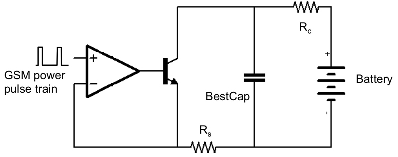
Verification in a real circuit From a mathematics standpoint, the reduction of overall power supply ESR must lead to an extension of time until violation of cutoff voltage occurs. In practice, whether this extension is sufficient to merit the addition of a supercapacitor depends on a number of factors: the current pulse parameters, battery and supercapacitor characteristics, and even user behavior (frequency and pattern of use). User-side variability is a topic left to the device manufacturer. Here, only current pulse parameters and battery and supercapacitor characteristics are considered. The circuit shown in figure 4 was used to investigate the effectiveness of using a supercapacitor in parallel with a battery in a GSM application.
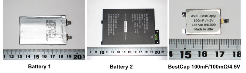
Two batteries were tested: 1000mAh / 3.7V and 1750mAh / 3.7V. The batteries were tested both with and without a 100mF /100 m? / 4.5V AVX BestCap® supercapacitor in parallel. A bipolar transistor was used as the electronic load, and was driven by an op-amp circuit, itself driven by a microcontroller, and the whole is configured to replicate a GSM current pulse. Feedback was provided by a 0.5? current sense resistor (Rs.). A 0.05? resistor (Rc) was added between the battery and BestCap® to simulate battery terminal contact resistance.
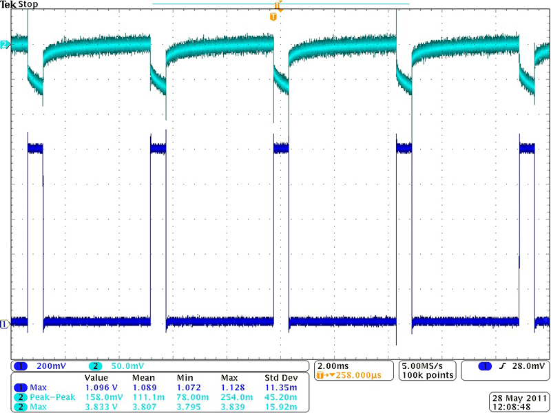
Figure 5 shows the 2A (Ch1 volts÷0.5?) GSM pulse (bottom) and line voltage (top).
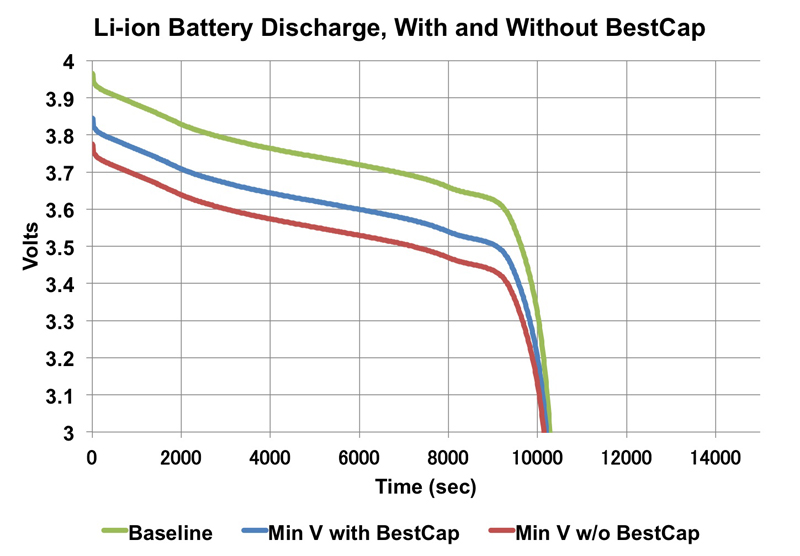
Results Figure 6 shows the discharge curves. The baseline curve was measured by data logger. The minimum voltage curves with and without BestCap® are derived from the baseline by subtracting the peak voltage drop when the current pulse is drawn.
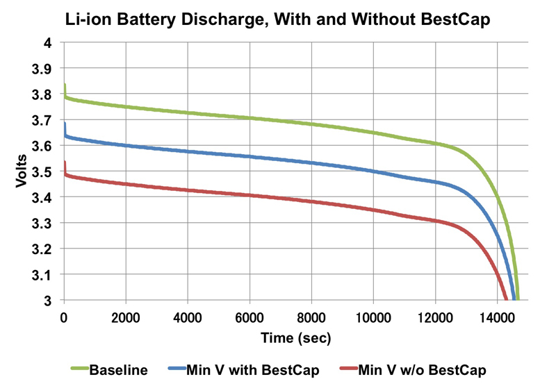
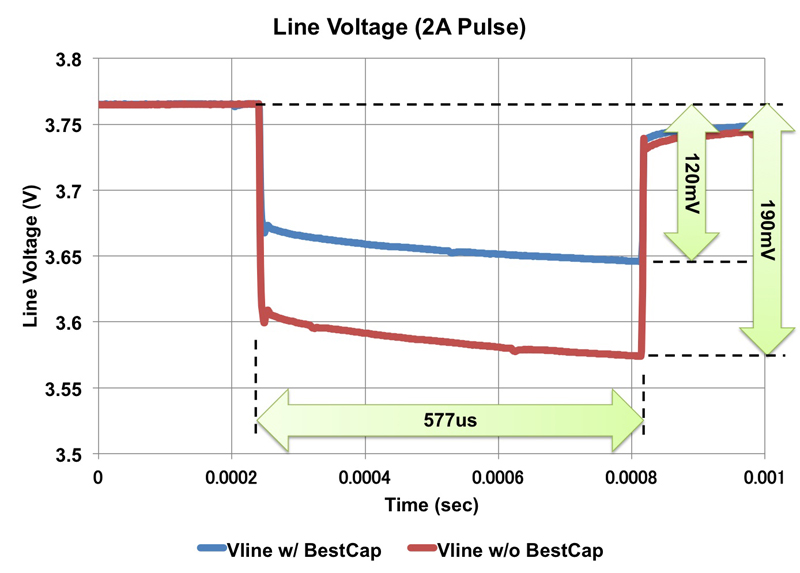
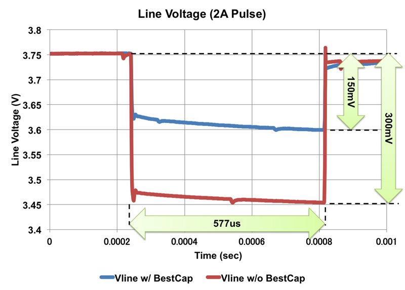
Figure 7 shows the voltage drop with and without BestCap®. For Battery 1, the addition of BestCap® reduced the voltage drop from 190mV to 120mV. For Battery 2, BestCap® reduced the voltage drop from 300mV to 150mV.

Battery life extension with BestCap® for a given cutoff voltage can be calculated by eq. 4. The plot is shown in figure 8. two: Time to cutoff without BestCap® tw: Time to cutoff with BestCap®
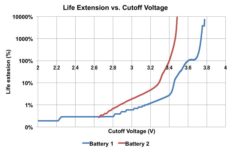
The two batteries exhibited very different discharge behaviors, but, in general, the higher the cutoff voltage, the greater the extension afforded by BestCap®. Life extension >10% occurs beyond about 3.45V for Battery 1, and 3.3V for Battery 2. There are two important points to be noted when considering these results. First, in these tests the current pulses were continuous throughout the discharge cycle. In a typical GSM application, the pattern is more likely one of intermittent use of the GSM function. Thus, unless there are other high current pulse functions in the same application, the realized life extension by adding BestCap® will be less than obtained in these tests. Second, many circuits, for example DC-DC converters, are "constant power" circuits, where greater current would be drawn with decreasing input voltage. In the tests described in this paper, a constant current was supplied from a steadily discharging battery. In the case of a constant power circuit, it is likely that the smaller voltage drop afforded by BestCap® would decrease the input current, and thus extend the life of the battery further. This aspect will be investigated in a future paper. Summary The addition of a supercapacitor, like AVX's BestCap®, can extend battery life in short duration, high current pulse applications. The degree of life extension in an actual application depends on many factors, including user behavior within the application. www.avx.com


