Automatic HVAC air recirculation with stepper motors
In most automotive HVAC systems, a continuous inflow of fresh air is conditioned and brought into the cabin. Typically the driver can select whether the fresh air supply needs to be interrupted (recirculation) or not (fresh air open). In recirculation mode, high-end HVAC systems monitor several cabin air parameters, recirculate the air through the air conditioning unit back into the cabin and limit the fresh air inlet to the minimum, while fulfilling the air parameters set by the driver and/or the system's specifications. Such automatic recirculation can reduce the fuel consumption of an HVAC system by 35%. Depending on the climatic conditions and driving cycles, an HVAC system can consume up to three litres of fuel per 100km. This indicates that large cars that are equipped with a low-end HVAC system will benefit the most from the addition of an automatic recirculation function. However, small- and medium-sized cars that have advanced engines with low emissions will also benefit from a smart air-recirculation flap because the contribution of the HVAC fuel consumption is relatively high. Forecasts indicate that the percentage of cars equipped with a semi- or fully-automatic HVAC system will increase year-on-year. At the same time, the introduction of CO2 refrigerants leads to the potential requirement for additional sensors to be mounted in the cabin. These trends mean that the CO2 and other fresh-air sensor technologies already available will increasingly be re-used in small cars and/or in cars with low-specification HVAC systems. While the sensor aspect of the automatic recirculation function may have been solved, there is still some work needed to tackle the issues around flap motorization
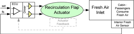
The HVAC Electronic Control Unit (ECU) closes the control loop of the fresh air regulation and operates the recirculation flap actuator (Figure 1) in order to maintain the required CO2 levels in the cabin. The frequency of operation of the circulation flap is a function of the maximum allowed number of occupants, the minimum volume of air in the car interior and the maximum allowed deviation from the desired CO2 level. It is easily calculated that five people in a 3m3 interior will increase the CO2 concentration by 100ppm within 30s.
The air recirculation control loop requires mainly low-speed interventions to compensate for pressure and airspeed changes in the "Fresh Air Inlet" (Figure 1). This happens frequently when the driving speed varies, for example in - or in the vicinity of - cities. The airflow also changes with automatic blower speed adjustments to cancel fluctuations in sun radiation (e.g. due to a winding road or intermittent shade caused by buildings, trees or clouds). The air recirculation flap actuator is a small motorized valve that is operated by means of a driver inside the ECU. For stable control algorithms, the flap position should be known at all times, so some sort of position feedback is a must. Because the control system is frequently re-adjusting the actuator position, contact-less operation of the motor and senseless position feedback is desired.
Several solutions exist to move HVAC air flaps, including the recirculation air flap. They differ in type of motor used in the flap actuator and the specifics and features of the motor control. We will now discuss three commonly used motor types. Brushed DC (BDC) motors are made in a mature and relatively inexpensive technology. Only two wires lead from the driver to the motor terminals. It is simple to control a BDC motor; e.g. bidirectional drive can be achieved by means of two transistor half-bridges. In case position feedback is required - as with the air recirculation flap - a position sensor needs to be added. A variety of sensors exist, the most common being potentiometers. This sensor together with the associated ECU wiring and the impact of the size of the electrical connector makes up a significant part of the system cost. It is also important to note that the brushes and commutator are the parts of a BDC motor that are most prone to wear. Because of the need for frequent operation of the air recirculation flap, brush degradation puts a stress condition on the long-term mechanical reliability of a recirculation flap equipped with a BDC motor. A unipolar stepper motor has two windings per phase. These windings are electrically connected with the ECU and, as with the BDC motor solution (with sensor position feedback), typically requires five wires. The choice of using unipolar stepper motors in motorized valves has mainly been dictated by the availability of low-cost driver ICs or driver circuits; e.g. a 4 low-side driver circuit. One drawback of the unipolar approach is that only half the number of windings is energized at any time (basically the unipolar stepper motor carries double the amount of copper than that required to move the motor). A bipolar stepper motor has one winding per phase. Compared to a unipolar motor, this gives a size and weight advantage because the amount of copper in the winding is roughly half of that for a bipolar motor with similar motor characteristics. The two windings are electrically connected with the ECU by means of only four wires (compared to five wires for a unipolar stepper motor or a BDC motor with sensor). A bipolar stepper motor is typically driven by a dual full-bridge transistor combination, one for each winding. Compared to BDC and unipolar stepper architectures, new bipolar stepper motor actuator technologies offer a balanced solution: more system benefits (i.e. an optimized mix of features and quality) without overall system cost penalties. The main reason for this is that bipolar stepper motors inherently contain a "virtual" sensor and the motor's operation modes (running at speed, stall condition, etc) can be deducted from monitoring the back-electro-mechanical force or the bemf signal.
An embedded stall detection algorithm based on the bemf signal, allows the system to detect very accurately the end-stop of a flap. Typically this end-stop is reached on purpose during a movement - for example when the flap is operated in a near-closed position. The closed-loop aspect (or merely pseudo closed-loop) consists of running deliberately into stalled condition once in a while. The stall detection then allows accurate marking of the new positions starting from the fully closed flap position. By doing this, even the smallest flap-openings can be maintained accurately and reached repeatedly, yielding true proportional control. It is clear that this mode of working offers advantages over traditional methods that utilize open-loop absolute positioning based on counting steps. Because to be sure that the end-stop is reached in a referencing run, these methods require driving the stepper motor multiple steps beyond the estimated end-stop position. This results in a blocked motor with associated acoustic noise and mechanical as well as magnetic wear-out. Now a device that detects the end-stop within one full-step will avoid the noise and vibration during the stall condition. Stall detection within a single full-step also allows the rotor and stator-magnetic fields to remain synchronized. This avoids any risk of magnetic wear-out caused by demagnetization of the rotor due to AC magnetic fields from the stator, and will help to maintain a stable actuator torque over life-time. Speed-critical positioning is important in situations in which a flap needs to be closed as fast as possible: e.g. closing of the recirculation flap when an exterior sensor detects the presence of polluted outside air. The back-emf signal makes speed critical operation possible for stepper motors by means of dedicated adaptive-speed motor drive algorithms. This allows stepper motors to challenge one of the main advantages of brush DC motor actuators, notably the ability to rotate as quickly as the supply voltage and load allows. The stepper motor is operated at the fastest speed possible, adapting speed automatically to the actuator and flap characteristics (e.g. load). During this adaptive-speed operation, sensor-less stall detection is operational, guaranteeing error-free positioning. These algorithms allow speeds up to 1000 full steps per second.
Table 1 summarizes the "fit for use" of the flap actuator technologies discussed. Both brush DC and unipolar stepper motors offer their advantages but also show weak points. The new bipolar stepper motor technology seems to offer the best of both worlds and is compatible with all reviewed requirements.

It is up to the Tier-1 HVAC system manufacturers to assign the correct weighting to all these functions. Observation: the system level cost is comparable for the three actuator types, however if only the purchasing cost of the motor driver itself is taken into account, then the car manufacturer might end-up with a sub-optimized solution.
Integrated circuits that drive bipolar stepper motors including the technologies described above are now available. A typical block diagram of such an IC is shown in Figure 2. This IC is placed inside the ECU and two full H-bridges drive the two phases of the bipolar stepper motor. The ECU's microcontroller communicates with the IC via an SPI interface and a set of dedicated signals. A current translator table, embedded in the driver applies the correct current to the windings. The microcontroller needs to set only once the SPI registers that define the winding current peak value, micro-step mode and default direction of movement. After this, the micro can step through the translator table by applying only "next" signals to the IC (see NXT pin in Figure 2). The motor driver then takes full responsibility and generates the requested current waveforms for full-step, half-step or sinusoidal micro-step motions. The speed of applying the "next" pulses defines the speed of the motor movement.
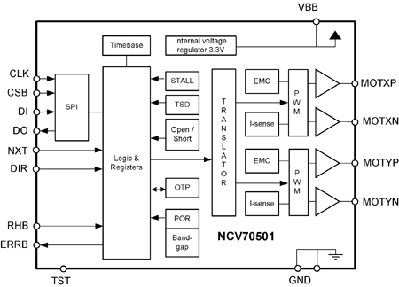
A simple but highly effective stall detection algorithm is implemented and can be activated by means of the SPI bus. The chip also supports an adaptive speed control function for closing the recirculation flap at maximum speed. Also proper diagnostic functions are implemented to detect all relevant error conditions and to prevent system and IC damage. The IC has an interrupt output pin to warn the microcontroller when an error occurs (see ERRB in Figure 2).
Automatic air recirculation valves can contribute to fuel economy of cars. Existing flap actuator technologies have been discussed in view of operating requirements of such a recirculation valve. Both brushed DC motor actuators and unipolar stepper motor actuators show incompatibilities with some of the technical requirements. A bipolar stepper motor valve in combination with a novel driver offers the best possible technical solution to meet the high-quality operation requirements of the air recirculation valves of the future. www.onsemi.com