What does it mean for semiconductor ICs?
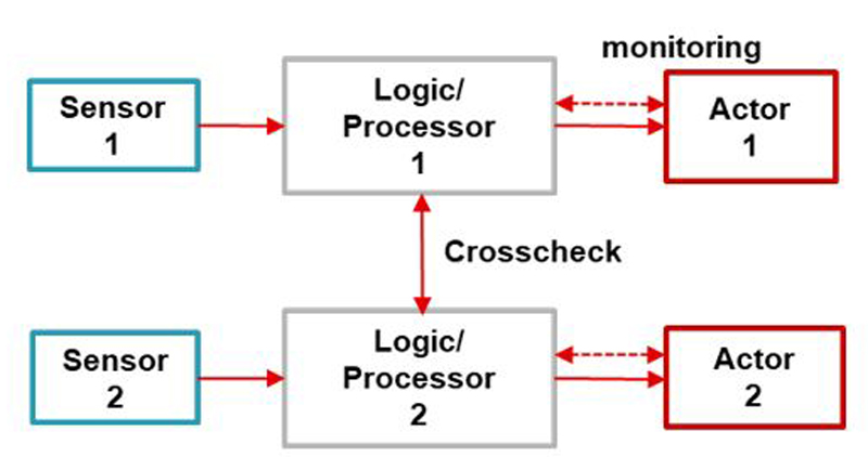
Figure 1: A dual-channel architecture to achieve HFT = 1
The need for industrial and automotive electrical and electronic systems to perform the intended functionality safely i.e., without causing hazards, is becoming important.
As industrial and automotive electrical and electronic (E/E) systems become more autonomous and complex, the need for these systems to perform the intended functionality safely i.e., without causing hazards, is becoming important. This approach, known as functional safety, is continuing to proliferate industrial and automotive applications. Standards such as International Electrotechnical Commission (IEC) 61508 for industrial systems and International Organization for Standardization (ISO) 26262 for automotive systems provide guidance not just for the systematic development of functional safety systems, but also quantitative metrics to determine a design’s effectiveness in reducing the risk of unintended behavior.
Semiconductor integrated circuits (ICs) play a key role in the design of E/E systems, and especially functional safety solutions. Different standards govern the implementation of functionally safe solutions in industrial and automotive systems. In this article we will explore the similarities and differences between ICs designed for an industrial application’s functionally safe system and ICs designed for an automotive application’s functionally safe systems. For this discussion, we will disregard the Automotive Electronics Council (AEC)-Q100 product qualification requirements for ICs targeted at automotive applications and instead explore this question only from an IC feature-set perspective.
Safety functions and safety mechanisms
Whether hardware or software, the components in E/E systems that enable a system to perform its intended functions are subject to faults. In certain cases, leaving component faults undetected or uncontrolled introduces a risk that the continued operation of a faulty E/E system could lead to dangerous and hazardous conditions, often necessitating additional components to detect faulty components and transition (or control) the E/E system from its current operating state to a safe state. These additional components are referred to as “safety function” in industrial functional safety standards and “safety mechanism” in automotive functional safety standards. Semiconductor ICs are key components to implement safety functions or safety mechanisms.
Using an electric motor control application as a case study, we will explore the similarities and differences between ICs designed for industrial systems and ICs designed for automotive designs
Electric motor control
Both industrial and automotive systems use electric motors and motor control E/E hardware and software. Industrial systems that use motor controls include industrial drives and robotics, while electronic power steering and traction inverters are examples of automotive systems with electric motors. The design of industrial and automotive motor-control E/E systems are similar, i.e., both must meet motor-control requirements, implement safety goals or requirements, achieve safe states in prescribed time durations, and include diagnostics for both the intended function and safety functions or mechanisms running at a required frequency. The design of functionally safe systems for both industrial and automotive applications must account for common-cause failures, cascading failure component failure modes and failure-in-time (FIT) rates.
However, we see the following differences between industrial systems solutions and automotive systems solutions:
· Concurrent safety standards: In contrast to the development of automotive safety systems, the design of safety-related industrial systems could use concurrent safety standards. IEC 61800-5-2 refers to the safety integrity level (SIL) per IEC 61508 as a target measure for the risk reduction with three levels, SIL 1 to SIL 3. On the other hand, ISO 13849 (safety of machinery) categorizes the residual risk of dangerous failures into performance levels (PL) from PL a to PL e, where PL e is equivalent to SIL 3. Therefore, industrial drive systems are often certified to be compliant with both mentioned standards.
· Specified safety functions and fault tolerance: Industrial functional safety standards, such as IEC 61800-5-2 for variable speed drives, are more specific and specified about safety functions. For example, the requirement for a shutdown function is well-defined in the standard as safe torque off (STO). The STO function prevents force-producing power from being provided to the motor. This safety function can be used where power removal is required to prevent an unexpected start-up. After the safety function is defined, the next step is to define the architecture. To understand this, we will consider safety related parts of a control systems (SRP/CS) as outlined in ISO 13849. In contrast to IEC 61800-5-2, ISO 13849 defines 5 categories which define the required behavior of the SRP/CS with respect of its resistance to faults. Therefore, it (the ISO 13849 standard) specifies the safety architecture that should be implemented including the minimum required hardware fault tolerance. A SIL 3 equivalent implementation with ISO 13849 would be PL e category 3, and requires a dual-channel architecture (HFT = 1), as shown in Figure 1.
· Availability of safety function: Most industrial systems implement HFT = 1, as specified by ISO 13849 for categories 3 and 4. This means that the safety function is always available, even when a single fault exists in the system. In automotive system designs however, HFT = 0 is often acceptable, which means that a safety mechanism could be unavailable when a single fault exists. The system treats such faults as latent faults, which are detectable either through diagnostic features or perceived by the driver. Figure 2 illustrates the difference between industrial and automotive system implementations.

Click image to enlarge
Figure 2: Safety function redundancy: an industrial system with an implemented redundant safety function (a); an automotive system without a redundant safety mechanism (b)
· Prescriptive process: Compared to industrial standards, the automotive ISO 26262 standard is less specific about safety mechanism requirements and implementations but is much more rigorous in defining the analysis and development process.. The standard rather assumes that the implementation of safety mechanisms depends on a system-level safety analysis and also accounts for the ability of the vehicle’s driver to perceive faults and mitigate unsafe operation when designing solutions.
· Diversity in implementation: Industrial standards such as IEC 61508 and ISO 13849 allow the use of the same component in both channels of a redundant design. A comprehensive procedure for measures against common cause failures (CCF) for sensors/actuators and separately for control logic is given, for example, in IEC 61508. With ISO 13849 common-cause measures need to meet a score of 65%. In contrast, the automotive functional safety standard does not typically allow the use of the same component in dual-channel systems, given the lack of diversity in systematic capability.
· Monitoring the safety function: In industrial systems, there is typically no concept of ignition cycles, since industrial machinery typically runs 24/7 year-round. Diagnostics or integrity tests of a safety function must be performed periodically while the system is operating. Diagnostic cycles in industrial drive systems could be as fast as 100 Hz to 1 kHz, which demands additional processing power if not implemented in hardware. In automotive systems, it is possible to perform diagnostics of the safety mechanism at every ignition cycle and still meet latent-fault architectural metric requirements.
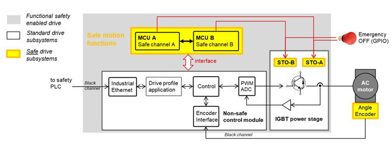
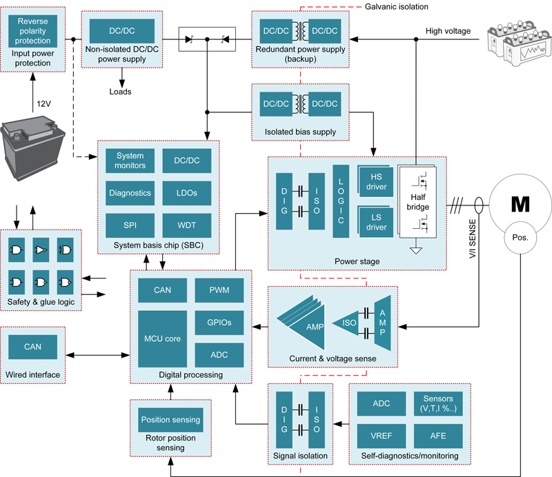
· Safety function integration: Figure 3 illustrates a modular approach with functional safety enabled industrial servo drives. There are typically multiple safety functions such as safe limited speed (SLS) and safe stop 1 (SS1) in addition to STO. The safety functions are typically enabled by using standard (non-safe) servo drives while connecting safety related programmable and non-programmable electronic add-on modules, which also include diagnostics such as cross-monitoring. In contrast, Figure 4 shows the implementation of an automotive traction inverter system. In this block diagram, the components responsible for the intended driving function, components that monitor the intended driving functions and components that monitor the safety mechanisms are regarded as a single system, which means that the safety mechanism is not an add-on.
Click image to enlarge
Figure 3: Block diagram of a safety-enabled industrial servo drive
Click image to enlarge
Figure 4: Block diagram of a typical automotive traction inverter
What does all of this mean for semiconductor ICs?
The answer is – it depends. However, we note that it is possible to use application-agnostic devices such as Texas Instruments (TI) C2000 microcontrollers in both industrial and automotive functionally safe systems by supporting built-in self-tests (BIST) of the safety functions, either at power up or during run time using safety-compliant software. The safety functions SS1 and SLS typically require safety MCUs, while the STO function today is often implemented in hardware without a safety MCU. A dangerous fault in the SLS and SS1 safety function, for example detected by the MCU BIST, could trigger the STO function, which will then transition the system to a safe state.
Similarly, it is possible to use a power-management IC (PMIC) with a voltage supervisor that has continuous monitoring of voltage supervisory functions in both industrial and automotive functional safety designs. Moreover, if a motor-driver IC implements a single safety function, the requirement of HFT = 1 necessitates the use of two ICs in industrial systems, whereas automotive systems may be able to use a single IC for an HFT = 0 design.
Finally, one more similarity to note: Both industrial and automotive safety system designers analyze for the effectiveness of the designed hardware architecture against random faults. In order to assess the effectiveness of the architecture, semiconductor component failure rates are needed to calculate the architectural metrics. In both automotive and industrial applications, designers typically decide between using component FIT rate for ICs calculated using either IEC TR 62380 or Siemens’ SN29500 standards. Therefore, semiconductor vendors typically provide the IC FIT rates calculated using methods described in both standards.
Conclusion
Semiconductor ICs play a key role in the design of functionally safe industrial and automotive E/E systems. This article discussed some differences between industrial and automotive functional safety standards in terms of specificity of the development process to address systematic design weaknesses and safety functions to address random faults. However, there are also similarities. Because of this, it is possible for a particular semiconductor component to be used in either automotive or industrial systems functional safety subfunction design – provided that the semiconductor component meets the diagnostics requirements, both method and monitoring frequency, of the safety functions/mechanisms.
TI categorizes its ICs as TI Functional Safety-Capable, TI Functional Safety Quality-Managed and TI Functional Safety-Compliant, regardless of the end application targeted for the IC. Furthermore, IC design engineers and E/E design engineers routinely leverage industrial and automotive safety function design principles using a broad portfolio of ICs available from TI for their functional safety designs.