Automotive high-current lighting demands advanced LED drivers
LED driver ICs must be designed to operate under a wide variety of environmental and electrical conditions
One of the biggest challenges for automotive lighting systems designers is how to optimize all the benefits of the latest generation of HB LEDs. HB LEDs require an accurate and efficient DC current source with a means for dimming and must include protection features. Additionally, these LED driver ICs must be designed to address these requirements under a wide variety of environmental and electrical conditions. As a result, power solutions must be highly efficient, low noise, robust in features and reliability, while also being compact and cost effective.
Arguably, the most demanding applications for driving HB LEDs are found in automotive forward lighting applications, in both DRLs and headlamps since they are subjected to the rigors of the automotive electrical environment, must deliver high power, typically between 15W to 75W, and must fit into very space constrained enclosures, all while maintaining an attractive cost structure.
Design Parameters
Automotive LED drivers must be compact, efficient and support flicker-free PWM dimming. They should not produce significant conducted EMI at and around the AM radio band. Unfortunately, low EMI is not in the nature of high power switch mode power supplies—the constant switching frequency produces a significant EMI signature at a number of frequencies, including the power supply’s fundamental operating frequency and its harmonics. Odds are good that something will fall into the AM band.
One way to minimize EMI peaks is to allow the switch mode power supply (SMPS) operating frequency to cover a range of values by incorporating spread spectrum switching. The desired effect of spread spectrum switching is to push down the EMI peaks that would occur at the SMPS fundamental operating frequency and harmonics, spreading the EMI energy over a range of frequencies instead.
LED driver SPMSs have an additional requirement: the frequency spreading should also be synchronized with the PWM dimming (brightness control) frequency to ensure that there is no resulting LED flicker.
To solve this problem, the LT3795 generates its own spread spectrum ramp signal and aligns it with the lower frequency PWM dimming input with a patent pending technique. This eliminates the chance that the spread spectrum frequency could combine with the PWM signal to produce visible flicker in the LEDs—even at the highest PWM dimming ratio.
High Power Automotive LED Drivers
The LT3795 is a high power LED driver that uses the same high performance PWM dimming scheme as the LT3756/LT3796 family, but with the additional feature of the internal spread spectrum ramp for reduced EMI. It is a 4.5V-to-110V input to 0V-to-110V output single-switch controller IC that can be configured as a boost, SEPIC, buck-boost mode or buck mode LED driver. It features a 100kHz to 1MHz switching frequency range, open LED protection, short-circuit protection, and can also be operated as a constant voltage regulator with current limit or as a constant current SLA battery or supercapacitor charger.
The LT3795 generates its own spread spectrum ramp signal and aligns it with the lower frequency PWM dimming input with a patent pending technique. This eliminates the chance that the spread spectrum frequency could combine with the PWM signal to produce visible flicker in the LEDs—even at the highest PWM dimming ratio.
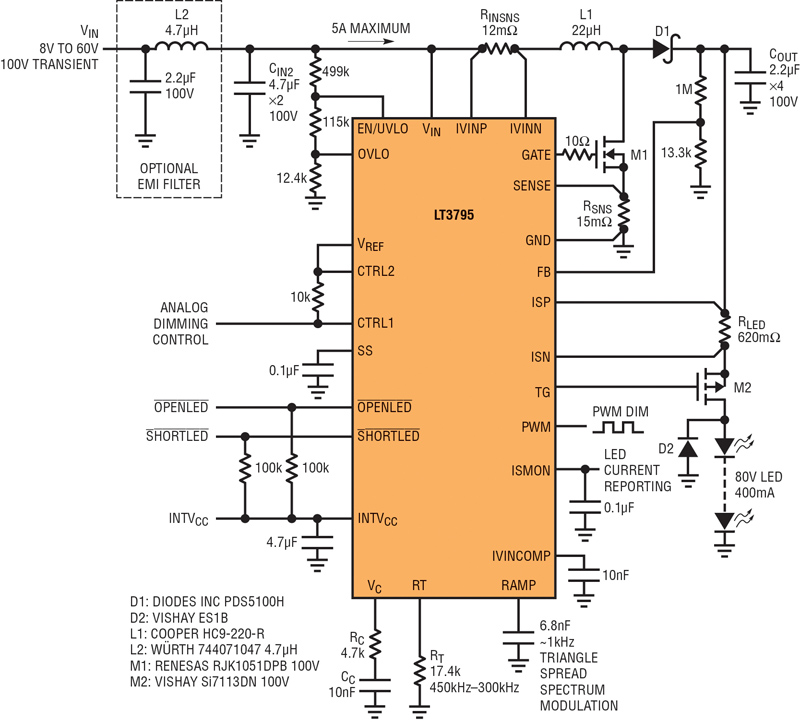
Figure 1 shows a 92% high efficiency 80V, 400mA, 300kHz-450kHz automotive LED headlamp driver with spread spectrum frequency modulation and short-circuit protection. A DRL application will looks nearly identical but with a maximum LED current requirement closer to 200mA.
Click image to enlarge
Figure 1
Internal Spread Spectrum Reduces EMI Issues
Unlike many high power LED drivers, the LT3795 generates its own spread spectrum ramp to produce 30% switching frequency modulation below its programmed switching frequency. This lowers its conducted EMI peaks, reducing the need for costly and bulky EMI input filter capacitors and inductors.
Using an external, or separate, spread spectrum clock to produce the switching frequency in an LED driver can produce visible flicker during PWM dimming since the spread spectrum frequency pattern is not synchronized with the PWM period. For this reason, in many high-end LED driver applications, implementing spread spectrum is non-trivial. Without spread spectrum, designers must rely upon bulky EMI filters, gate resistors that slow down switching edges (which reduces efficiency) and snubbers on the switch and catch diode.
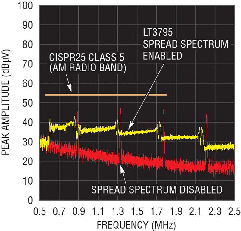
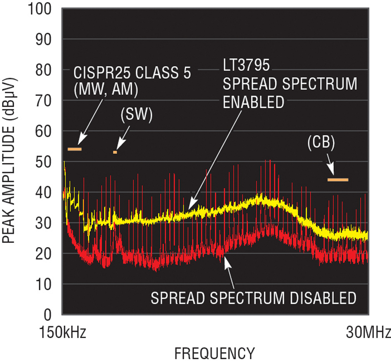
Figure 2 shows a comparison of the conducted EMI measurements of the LT3795 LED driver around the AM band when spread spectrum is enabled and disabled. Normal (non-spread spectrum) operation yields high-energy peaks at the switching frequency and its harmonics. These peaks can prevent the design from passing stringent EMI requirements in EMI sensitive applications such as automobiles. For reference, the CISPR 25 class 5 automotive conducted EMI limits are shown in Figure 2. Figure 3 shows the effect of spread spectrum over a wider frequency band.
Click image to enlarge
Figure 2
Click image to enlarge
Figure 3
Since there is no limit between 300kHz and 580kHz, this is an excellent range for the fundamental frequency to be placed. In this application it is placed at 450kHz and spreads down to 300kHz. Simply grounding the RAMP pin can disable spread spectrum.
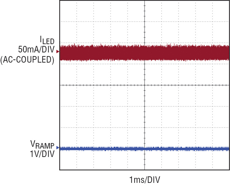
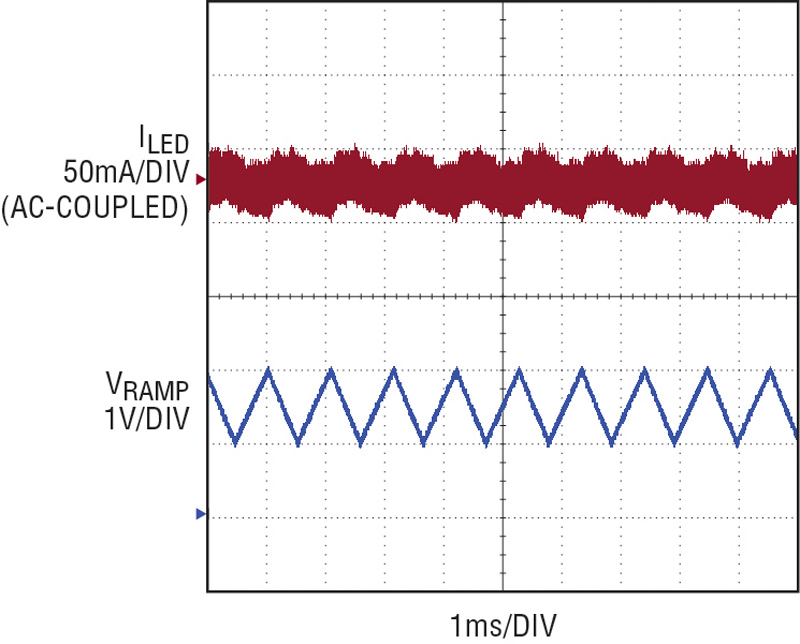
The 6.8nF capacitor at the RAMP pin sets the spread spectrum frequency modulation rate to a 1kHz triangle—that is, the LT3795’s operating frequency sweeps from 300kHz to 450kHz and back every millisecond. The addition of the triangular 1kHz spread spectrum signal has a negligible effect on LED ripple current, as shown in Figure 4.
Click image to enlarge
Figure 4a
Click image to enlarge
Figure 4b
The modulation frequency of 1kHz is chosen because it is low enough to be within the LT3795’s bandwidth, yet high enough to significantly attenuate AM-band conducted EMI peaks. Further reducing the modulation frequency degrades peak attenuation in the AM band, where it may be most important for classification. The choice of spread spectrum modulation frequency does not appear to affect EMI peak attenuation at higher frequencies. The human eye can’t perceive anything above 100Hz.
Flicker-Free PWM Dimming
It is possible to reduce EMI with a spread spectrum source that is not synchronized with the PWM signal, but the beat of the switching frequency and PWM signal can produce visible flicker in the LED. The spread spectrum ramp generated inside the LT3795 synchronizes itself with the PWM period when PWM dimming is used. This provides repeatable, flicker-free PWM dimming, even at high dimming ratios of 1000:1.
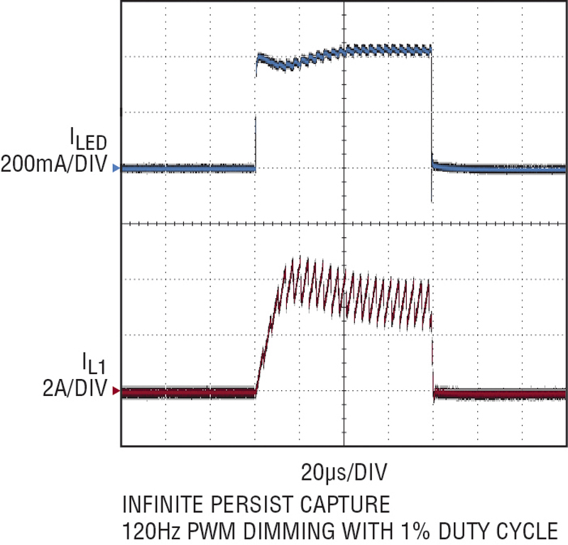
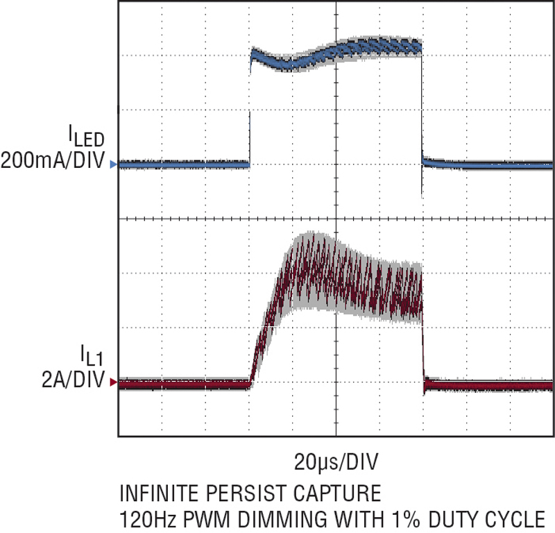
Figure 5 compares the PWM dimming current waveforms of two spread spectrum solutions: one with the LT3795’s patent-pending spread-spectrum-to- PWM synchronization technique, and one without. Both scope captures are produced with infinite persist, showing an overlay of a number of cycles of a 1% PWM dimming waveform. Figure 5(a) shows the result of LT3795’s spread spectrum operation on the PWM LED current. The waveform is consistent cycle-to-cycle, which results in flicker-free operation. Figure 5(b) shows the results of a comparable, non-LT3795, spread spectrum solution. The cycle-to-cycle variation in on-time shape produces variation in average LED current, which can be seen as LED flicker at high dimming ratios.
Click image to enlarge
Figure 5a
Click image to enlarge
Figure 5b
Note that spread spectrum driver ICs without the LT3795’s patented technique might produce a clean spread spectrum EMI reduction result; the flicker may still be present. One has to observe the LEDs or the LED current waveform to understand if flicker is present. In the case of the LT3795, both the conducted EMI scan and the scope shot of LED current are good.
Short-Circuit Proof Boost
The LT3795 boost LED driver shown in Figure 1 is short-circuit proof. The high side PMOS disconnect is not only used for PWM dimming, but also for short-circuit protection when the LED+ terminal is shorted to ground. Unique internal circuitry monitors when the output current is too high and the LED+ voltage is too low, turns off the disconnect PMOS and reports a short LED fault. Similarly, if the LED string is removed or opened, the IC limits its maximum output voltage and reports an open LED fault.
Multitopology Solution
The LT3795 can be used to drive LEDs in a boost setup as shown in figure 1, or it can be used in buck mode, buck-boost mode, SEPIC and flyback topologies when the relationship of the LED string voltage and input voltage ranges requires it. All topologies feature the same spread spectrum and short-circuit protection. The LT3795 can even be configured as a constant boost or SEPIC voltage regulator with spread spectrum frequency modulation.
Conclusion
The continual acceleration of HB LED applications, especially those found in automotive DRLs and headlamps are being driven by an insatiable demand for higher performance and cost effectiveness. Robust HB LED driver ICs must enable these demands. LED drivers such as the LT3795 offer solutions for applications with inputs up to 110V. It also offers built-in spread spectrum frequency modulation to reduce EMI. This simplifies the design of LED applications that must pass stringent EMI testing. Spread spectrum requires only a single capacitor, and unlike external-clock-based spread spectrum solutions, produces flicker-free LED operation during PWM dimming. Short-circuit protection is available in all topologies, making this IC a robust and powerful solution for driving automotive LEDs.
 Single.jpeg)