Automotive Lighting - HID Applications
HID applications: ballast and igniter
Figure 1: Ballast-Igniter Circuit
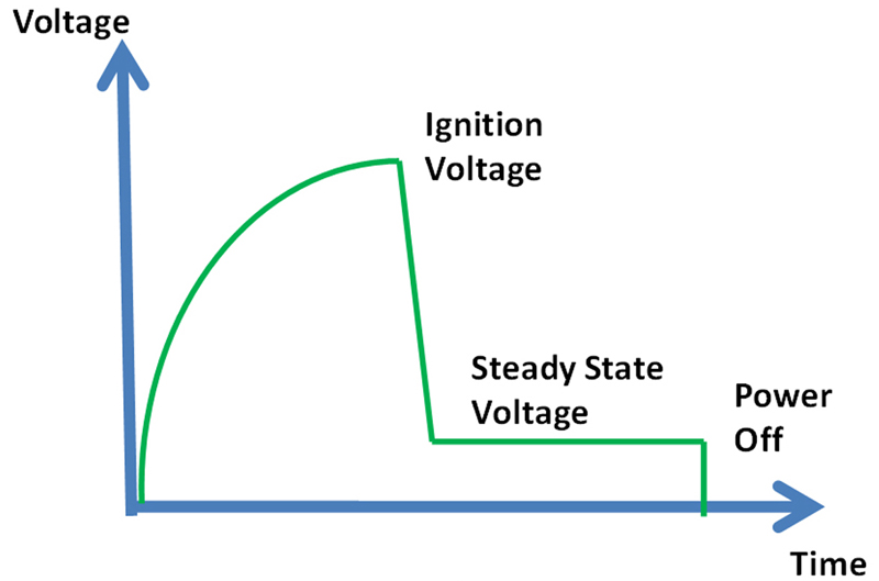
High Intensity Discharge (HID) headlamps are superior replacements for conventional heated-filament headlamps that require about 25kV applied to the lamp electrodes to ionize the Xenon gas and ‘strike' an arc. HID technology simply uses the light emitted when ionized Xenon gas in a sealed bulb changes energy states. Once the gas is initially ionized, the light-emitting arc is sustained by an AC potential of about 90V applied across the electrodes in the bulb. The resulting arc emits light with a high luminous intensity, hence the name High-Intensity Discharge or HID. The HID lamps consist of the following units: Ballast, Igniter, and Bulb. A simplified equivalent circuit is given in Figure.1. The ballast is comprised of the DC/DC converter, which can boost the battery voltage up to the HID lamp voltage and the DC/AC inverter. For the starting of the HID lamp, the DC/DC converter increases the input voltage of the igniter to reach the Breakdown Voltage of the arc gap.
KEMET film technology department has developed two special series for the HID Xenon headlamps (see Figure 2): Igniter: HNS - film naked capacitors using stacked technology (high peak currents withstanding) available in SMD and in leaded version made with PEN dielectric able to work up to 170°C. Ballast: SWN - SMD film naked capacitors using wound technology made with PEN dielectric able to work up to 150°C and focused on withstanding high voltage peaks during the ignition phase. Igniter unit The igniter capacitor must be able to support high voltage, high currents and critical humidity environment. Due to the fact the ignition circuit is usually integrated with the Xenon lamp, the max ambient temperatures surrounding the capacitor could reach 170°C and the dimension of the capacitors should be as low as possible. The SMD technology requires the LF reflow process. In order not to decrease the efficiency of the igniter circuit, high capacitance stability is required. Considering the harsh automotive environment, several tests in severe humidity conditions (loaded, up to 85°C - 85% RH) are carried out without any significant capacitance drop up to 1000h. A critical parameter for the igniter capacitor is the voltage withstanding, especially after the LF reflow process. In order to monitor the igniter capacitor performance from this point of view, a voltage value is recorded to indicate the first occurrence of partial discharges when a constant voltage ramp-up is applied on the capacitor (First Breakdown Voltage - FBDV). What is measured in this way is not the real ‘breakdown' of the dielectric, but only a partial discharge that, in some cases, can create only very small and brief current flow. The FBDV results recorded after the solder-reflow process with different peak temperatures (233°C and 245°C) have shown that the first partial discharges appear for voltages higher than 1300Vdc.
Ballast unit In the equivalent circuit of the ballast of Figure 1, the capacitor C1 filters the current pulse from the flyback inverter running at hundreds of kHz. This capacitor provides the initial current to the lamp during ignition. The energy stored in the C2 boost capacitor assures good heating of the lamp electrodes and completes the glow to arc transition of the HID lamp. The max ambient temperature for the ballast is usually 125-135°C due to the non-proximity of the ballast to the lamp. The main requirements are small dimensions, withstanding voltage peaks (300 to 600V), critical humidity environmental conditions, and LF reflow process. Wound technology was chosen for its intrinsically good performances in withstanding voltage peaks. Since the withstanding of voltage peaks and the dimensions were the main application requirements, efforts have been focused on these characteristics, with the result of reducing the film thickness by about 33% from the general-purpose SMD naked stacked PEN capacitor. This dramatically reduces the volume of the capacitor, leads to increasing capacitance range, and significantly improves the FBDV results. The boost capacitor's working temperature is currently up to 125°C, but with the upcoming new 25W version, the integration between the igniter and the ballast circuits might be an option. For this reason, the boost capacitor's working temperature can rise up to 150°C, validating even more the choice to use the PEN dielectric. KEMET has also developed a special SMD leaded multilayer ceramic capacitor series (KPS AUTO). These ceramic capacitors can be operated reliably above 125oC but to achieve the high capacitances required by many designs, larger case sizes must be used and this presents another set of challenges. Unlike film capacitors, there is no self-healing mechanism in MLCCs so the parts must be designed to be robust and applied such that they are not over-stressed in the application.
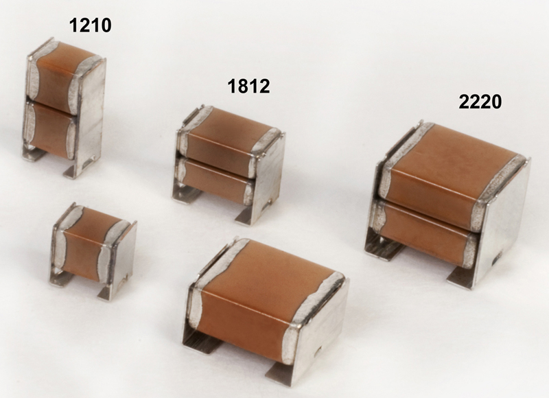
The J-lead allows two MLCCs to be placed in the same pad space on the circuit board doubling the capacitance compared to using one. The J-lead also adds significant compliancy that prohibits cracking of the ceramic during board flexure so the KPS AUTO can tolerate flexures 3X higher than the MLCC mounted directly to the circuit board. The leads also allow these parts to tolerate a significant mismatch in the coefficient of thermal expansion (CTE). The MLCC typically has a CTE ~ 10 PPM/oC or less compared to 15 PPM/oC for FR4 or above this for various insulated metal substrates. These differences are magnified for larger capacitors. Rapid thermal cycling of the assemblies can cause the ceramic to crack in the MLCC whereas the J-leads additional compliancy absorbs this mismatch in KPS AUTO. The break strength is also an important consideration and this depends on the type of ceramic dielectric used. KPS AUTO has two alternative dielectrics, X7R and C0G. The C0G has twice the break strength of X7R in the larger 2220 case size. Although the X7R has lower break strength, it also has higher capacitance. The capacitance of X7R declines significantly with applied voltage and at temperatures of 150oC. This combined effect can reduce the available capacitance by up to 70% compared to the nominal value for X7R. These make X7R appropriate for ballasts that are not exposed to large mechanical stresses or thermal shock. The C0G has much higher break strength and does not experience any significant loss of capacitance with temperature or voltage. The insulation resistance of C0G remains high at 150oC, making this preferred for high temperature applications that require robust mechanical performance. The development of KPS AUTO supports the demand for higher temperature designs. When combined with films KEMET can now support a broader capacitor design space for automotive HID headlamps. www.kemet.com

.jpeg)
 Single.jpeg)
