Protection modes on programmable power sources can save valuable engineering prototypes and development time.
Figure 1: Constant voltage mode operation
This article explains the various functions available to the user of a programmable AC power source to protect the unit under test against various overcurrent and overpower conditions that could cause it to get damaged. An overview of commonly found protection modes is provided first to set a baseline, followed by some new and advanced additional levels of protection offer by new advanced power source designs like the AFX Series from Pacific Power Source.
Commonly Available Protection Modes
Conventional programmable AC or DC power sources typically offer one or two current limit protection modes. The most commonly used method is known as constant current mode or CC mode.
Constant Current Mode
Constant current mode relies on a programmable current level that can be set anywhere from zero to the maximum current value that can be supplied by the power source. For example, a 3 kVA power source with a 150V voltage range can deliver 3000 / 150 = 20 A max. Thus, the CC mode level can be set anywhere between 0.0 and 20.0 A. As long as the load current remain below CC set point, the output voltage is held at the programmed value. This means the power source operates in a constant voltage mode in normal operation.
When the load current exceeds the CC mode level programmed however – e.g. 120 V - the power source will transition from this constant voltage mode to a constant current mode of operation. It does so by reducing the output voltage enough to get the current back to the CC current trip level. Thus, if the impedance of the load drops below 120/20 = 75 ohm to 50 ohm, the output voltage is reduced to 100 V. This will maintain the load current at 20 A as programmed.
Constant Voltage Mode
An additional protection mode is often available on programmable power sources called CV mode, which is a variation of CC mode. In this mode, the load is protected not by just limiting the maximum current to the CC set point but is further protected by shutting down the output of the power source entirely. This type of current trip mode implied the power source is always operating in constant voltage mode as described in the prevision section. If the load current exceeds the CV current threshold level, the output is dropped to zero and the output relay – if present – is opened to disconnect the load.
This mode is more useful if the load is to be protected at all cost from any condition that exceeds a certain current trip level. In his so call constant voltage or CV Mode, rather than holding the current to the load at the programmed current limit level indefinitely by adjusting the output voltage down as needed, the load just shuts down if the set current level is exceeded. More advanced AC sources may support a user programmable CV trip delay to prevent so called nuisance tripping at the current limit level. Once this delay expires and the current is still above the set point, the output turns off.
Advanced Design Enables Additional Protection Modes
Pacific Power Source’s AFX Series is based on an all-digital control power conversion platforms and not limited to only using the two aforementioned current based protection schemes. Due to its advanced design, it monitors all output parameters and load conditions every cycle and can made decisions based on more than just RMS current.
This enables the following additional levels of protection for the unit under test:
· Power protection
o True Power (kW) protection
o Apparent Power (kVA) protection
· Cycle-by-Cycle Peak Current protection
Power Protection Modes
Many AC power products in today’s world are capable of operating over a much wider AC input operating voltage range than before. This allows such equipment to be used a wide variety of locations where utility voltages vary from country to country. It is not uncommon that have an AC powered product that operates from 85Vac all the way up to 264Vac. When developing or testing these types of product, the typical RMS current limit protection found on traditional programmable power source is not effective. If the EUT can draw 3000 W at 115V, the current limit would have to be set at 3000/115 = 26 Arms to prevent damage to this EUT in the event of a failure condition. However, the same EUT operating at 240Vac would be able to pull up to 240 x 2.7 = 6,240 W before the power source’s current limit would kick in to protect the EUT. By then, the damage is most likely already done.
This type of EUT requires a programmable power limit function. By using a power limit function, the voltage can be varied during testing without having to be concerned with any damage caused by an unexpected fault in the EUT. No matter where the test voltage and current are at any time, the protection will always kick in at the same power level.
The effect of a programmable power limit function is illustrated in the chart below which shows the power limit curve of voltage versus current and the ability to shift the curve up or down by programmable the desired power limit level. Once the EUT power consumption reaches the set level, the AC source will adjust its voltage as needed to keep the power level at this value.
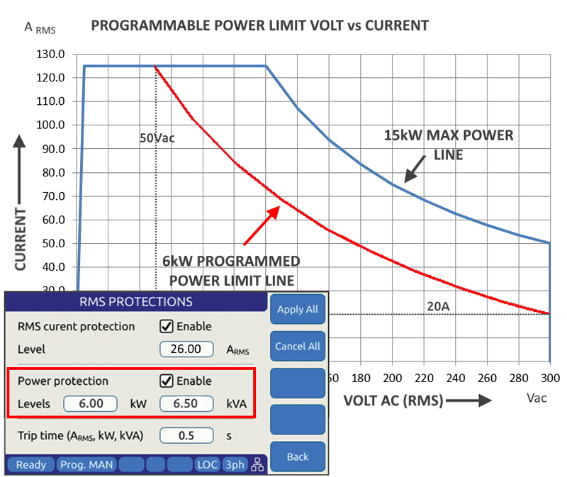
Click image to enlarge
Figure 2: Programmable power limit set to 6kW on a 15kW AC source
The AFX has both true power and apparent power limit programming capability and either one or both can be used at the same time if needed. Thus, if the power factor of the EUT is known, both Watt and VA limits can be set independently. The setup for this function is accomplished directly from the main program screen as shown below.
If it is not acceptable to have the EUT operate when drawing more than the set power limit, the output can be tripped off after a pre-set delay. The delay prevents nuisance tripping during short duration power surges that only exceed the trip threshold for a short period of time. A trip condition is considered an EUT fault and the output remains off after a trip until re-enabled by the operator or a test program.
Peak Current Protection Mode
Peak current protection is quite different from RMS levels protection and only applies to AC power sources, not DC power supplies as AC current typically has a crest factor of 1.414 or higher. Since the AC current’s peak value is determined by the nature of the load connected, limiting RMS Current or Average current does not say anything about the maximum peak current the load will draw. If a failure or other condition occurs in the load that causes the current crest factor and thus the peak current to rise, a normal AC source will not protect the EUT as long the RMS current remains at or below the RMS current limit set point.
This is where user programmable peak current protection comes in. By setting the maximum allowable peak current, the end user can control how much peak current is allowed to go into the EUT. The allowable setting is is from zero to the maximum peak current the AC source is capable of supporting by design. This peak current set point can be multiple of the RMS Current set point for non-linear loads with high crest factors.
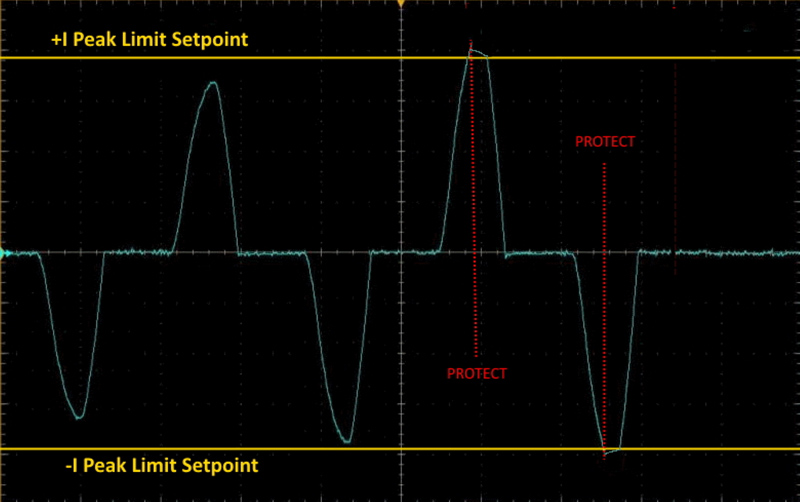
Click image to enlarge
Figure 3: Peak current protection in effect
Conclusions
Protecting valuable equipment under test, especially when dealing with early engineering prototypes is critically important as the accidental loss of a prototype can set back product development cycles by weeks or months, as the EUT is reworked or worst case completely rebuild or replaced.
Have a wide array of protection modes beyond the basic current limit function found on most conventional AC power sources is an important consideration when selection your next project’s AC Power source. Spending some time investigation and reviewing alternative can pay big dividends during product development an product test later on.
If you are not sure, discuss your needs with your test equipment vendor’s technical staff as they often have experience gained from similar discussions with the other customers.
Pacific Power Source, Inc.