Avoiding Field Failures with Crowbar Protection Thyristors
Product failures in the field are both expensive for the manufacturer and create a customer perception of poor quality
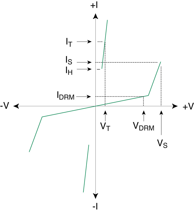
Figure 1. SIDACtor I-V Curve. It is a bipolar device with an off-state and an on-state. VDRM is the maximum off-state voltage. In that state, the maximum current, IDRM is the off-state leakage current. When the voltage across the device reaches the breakover voltage, VS, the device switches to the on-state and conducts a large current, IH, the holding current. The SIDACtor maintains the holding current at a low voltage, VT, the holding voltage. The SIDACtor can maintain a large current with its power capacity due to the low crowbar voltage, VT.
Ensuring a product is robust to power line transient conditions is a critical aspect of design that often does not receive the appropriate level of attention during product design. While a product failure due to a high voltage transient is an external event, the failure is due to a design that inadequately protects the internal circuitry of the product. Thus, power line surge protection is an essential element to ensure a robust AC line-powered device.
Potential sources of high voltage transients are weather conditions. Lightning can induce high voltage and current surges on a power line. Damage to power lines resulting from construction errors or traffic accidents can also cause large transients. Even when there is no problem, the de-energizing or de-powering of a high current load such as a large motor will create a transient on the power line due to the di/dt current reduction from the large load. Transient peaks also can result from current flowing through higher than normal impedances on neutral lines or from single-phase faults on a 3-phase power system.
High voltage transients can damage a product, leading to an in-warranty repair failure and an unhappy customer. Resolving the problem for the customer can be an expensive service; and the manufacturer can experience the potential loss of future business from a disappointed customer.
Surge protection is the methodology to protect products against damage from high voltage transients. The transients can cause intermittent errors in data transfer or permanent damage to the product. Fortunately, there are components available which provide protection from high voltage transients.
There are options for power line surge protection design and the design engineer should be aware of the advantages and disadvantages of each option. The options include over-voltage protection components such as metal oxide variators (MOVs), transient voltage suppression (TVS) diodes, gas discharge tubes (GDTs), and protection thyristors or Silicon Diodes for Alternating Current (SIDACs). Littelfuse, a manufacturer of circuit protection devices, manufactures a unique version of these devices under the trade name, SIDACtor®.TVS diodes and MOVs are clamp-type components, while GDTs and protection thyristors are crowbar-type devices. Clamping, in this application, is defined as holding the voltage across the component at, approximately, a fixed level when the component’s overvoltage threshold is exceeded. Crowbarring refers to limiting the voltage to a small value when the component’s overvoltage threshold is exceeded. A crowbar device effectively turns on like a digital switch in response to an overvoltage.
Clamp-type devices have faster response times, but they are limited in their current handling capacity. These devices also have a clamping voltage that is a function of conducted current. Since the clamping voltage is higher than the voltage that a crowbar device would have when both devices are in their overvoltage protection state, the clamping device will allow a lower peak current for a high voltage transient.
The crowbar-type devices can handle much higher surge currents since the clamp voltage is very low when the device switches to its on-state. The near-short condition shunts the transient energy away from the circuitry of the product. The low voltage that the crowbar component presents to the product circuitry further reduces any stress on the product.
MOV and TVS components, the clamping-type protection devices, can handle high peak currents. MOVs can withstand transient current peaks up to 70kA. They are low cost protection devices, but they do have the disadvantage of higher off-state leakage currents. TVS components do not have the peak current capacity of the MOV, they do have a lower on-state clamp voltage. The TVS devices have a longer lifetime than the MOV devices as MOV devices can be degraded by sustained overvoltage conditions leading to excessive heat dissipation in the device. Both MOV and TVS components have higher parasitic capacitance than crowbar-type devices which allows high overshoot when subjected to high dv/dt or high di/dt transients.
The two clamp-type components, the GDT and the SIDACtor, are significantly different. The SIDACtor is a semiconductor device while the GDT relies on a gas to break down and conduct current when a threshold voltage is reached. Similar to an MOV, the GDT has a limited lifetime based on the number of times the gas is ionized and conducts. The gas is adsorbed on the electrodes after it is ionized. The GDT can withstand large peak currents, but has a much slower response time than the SIDACtor. The GDT cannot prevent very narrow high voltage transients from passing through to the product.
Of the four surge protection components, the SIDACtor has the best combination of properties for AC power line protection. It offers a long lifetime independent of the number of high voltage transients to which the device is subjected. The SIDACtor has a low on-state crowbar voltage level and a fast turn-on characteristic. It has the least overshoot for high dv/dt or high di/dt surges and a low, off-state leakage current. Table 1 compares the four types of protection devices.

Click image to enlarge
Table 1. Characteristics of four high voltage transient circuit devices. The GDT and SIDACtor crowbar the transient to a low voltage. The MOV and TVS clamp the transient to a fixed voltage level
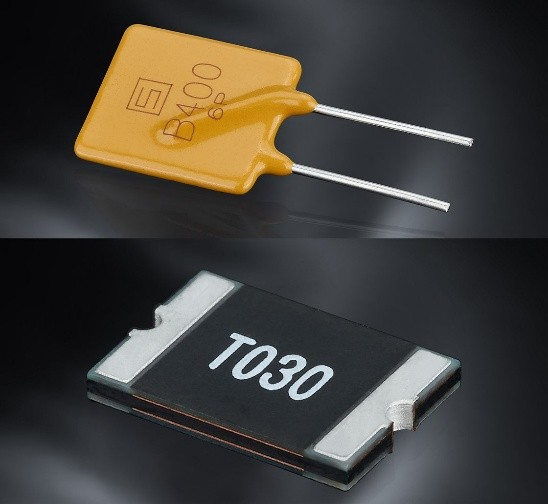
Figure 1 shows the characteristic curve for the a SIDACtor. Below VDRM, the maximum off-state voltage, the SIDACtor has a low leakage current, IDRM. The Leakage current is on the order of a few microamps. When the voltage reaches, VS, the device’s peak threshold voltage, the device turns on and switches to a low holding voltage, VT. The SIDACtor can support a large transient current since the voltage across the component is crowbarred at the low voltage, VT. A SIDACtor that can handle a peak surge current of 5000A is housed in a standard TO-218 case for easy printed circuit board layout.
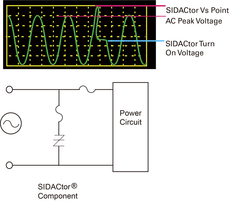
Fortunately, fully protecting devices from high voltage transients takes only a few components. Figure 2 shows a 3-component solution for protecting a product’s power circuitry. The SIDACtor is paralleled with the power circuit to provide protection from a transient on the AC power line. Since the SIDACtor is in parallel with the power circuit, the SIDACtor has no effect on the performance of the product when no high voltage transients are on the AC line. The SIDACtor, with its low leakage current, consumes only milliwatts of power at nominal AC power line voltages. The fuse in series with the SIDACtor protects the component from a current surge lasting a single, complete AC line cycle or multiple AC line cycles. The series fuse provides traditional overcurrent protection for the power circuit. The series fuse is placed after the SIDACtor circuit to protect the fuse from high voltage transients. This 3-component network provides both overvoltage and overcurrent protection for the power circuit.
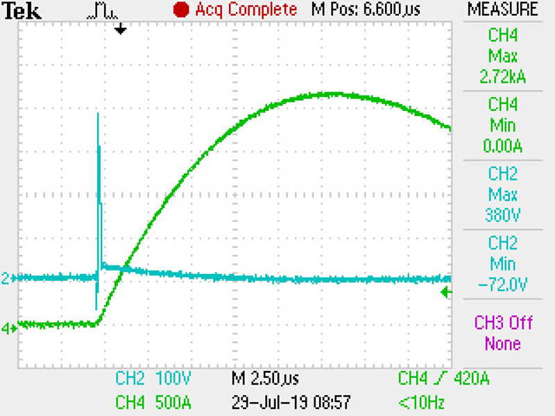
Figure 3 shows the SIDACtor’s fast response to an AC line transient. The green curve is the high current waveform resulting from the voltage transient. The blue line shows how the SIDACtor quickly responds to crowbar the voltage to a safe, low level for the power circuit.
Click image to enlarge
Figure 2. Protection network using a SIDACtor for high voltage transient protection, a fuse to protect the SIDACtor from a sustained overvoltage condition, and a fuse for protection of the power circuit from an overcurrent condition
Click image to enlarge
Figure 3. SIDACtor response (blue trace) to a current surge (green trace) resulting from a high voltage transient
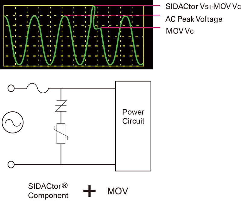
A SIDACtor can also be used in combination with a MOV to provide low voltage clamp protection for circuits that can be damaged by high clamping voltages. See Figure 4. The impedance of the MOV lowers the maximum current following a transient by a factor of at least five which lowers the total instantaneous energy absorbed by the SIDACtor and ensures the SIDACtor is protected. A second important advantage of the combination is that the leakage current is lower than the leakage current drawn by the MOV by itself. For products that must meet low power consumption standards, minimizing the leakage current drawn by the device when it is in its off state or standby state is essential for maximizing power efficiency.
Click image to enlarge
Figure 4A. A protection network using a SIDACtor in series with a MOV. The fuse provides overcurrent protection
Click image to enlarge
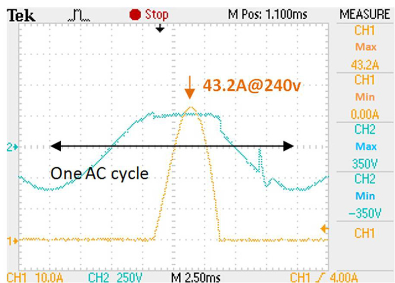
Figure 4B. The SIDACtor-MOV series combination limits a transient with a 3kA surge to only 43.2A (orange trace). The blue trace shows the transient voltage clamped by the MOV
An inverter, Figure 5, is an application that can use a SIDACtor-MOV combination for AC power line surge protection. The SIDACtor-MOV combination protects the inverter drive circuitry from differential high voltage transients. Parallel MOVs protect against surges in the neutral-to-ground connection when the AC mains have a relatively high impedance for neutral lines. For inverters powered by three-phase AC lines, a SIDACtor-MOV combination is recommended for each phase of the three-phase AC line. This protection topology is also recommended for use in electric vehicles and hybrid electric vehicles as well as for photovoltaic-powered inverters.
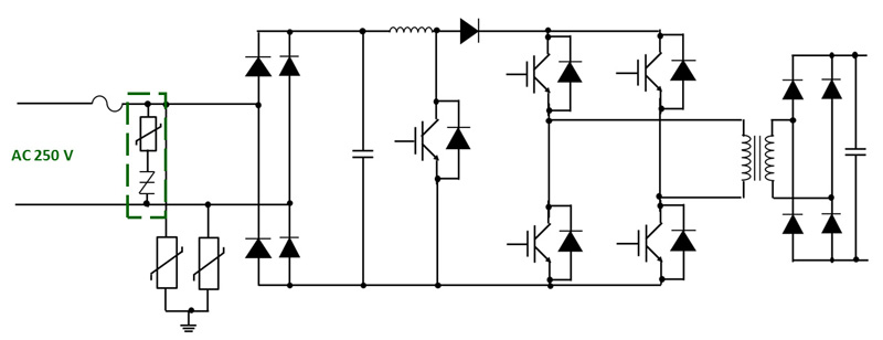
Click image to enlarge
Figure 5. A recommended protection network for a power inverter circuit includes a MOV and a SIDACtor in series for line-to-line protection and an MOV pair for line-ground protection
There are a number of different components that provide levels of protection from high voltage transients. For AC power line protection, the SIDACtor is the most cost-effective component available on the market. It features a low on-state crowbar voltage, fast response to a transient event, long life, and can withstand a high surge current. Combined with fuses for overcurrent protection, the SIDACtor or the series combination of a SIDACtor-MOV provide an excellent and simple protection network for a product’s power circuit.