Author:
Bruce Haug Sr. Product Marketing Engineer, Power Products, Linear Technology Corporation
Date
05/02/2017
 PDF
PDF
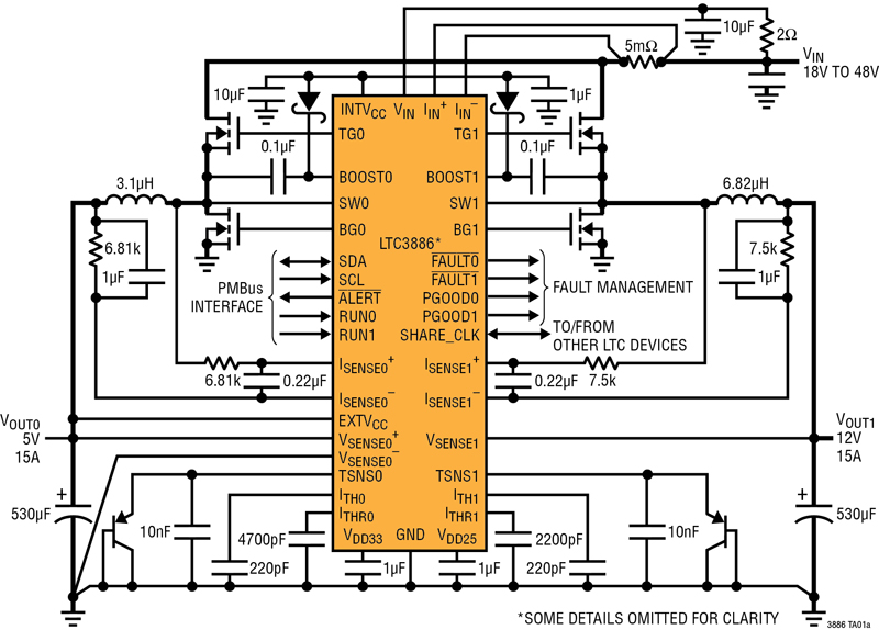
LTC3886 Schematic Converting 48VIN to 5V/15A & 12V/15A
Knowing the condition and operating status of a voltage regulator is perhaps the last remaining blind spots in today’s modern electronic systems since they do not normally have the means for directly configuring or remotely monitoring key operating parameters. It’s usually critical for reliable operation when regulator output voltage drifts or during an over temperature condition, it must be detected and acted upon before a potential failure event occurs.
Digital Power System Management (DPSM) allows designersto simplify and accelerate system characterization, optimization and data mining during prototyping, deployment and field operation.A DPSMapproach to such systems can monitor the performance of a voltage regulator and report back on its health in so that corrective action can be taken prior to it going out of specification or even failure. DPSM allows users to act upon the information collected from the load and the system with the following benefits:
Digital control over analog power supplies with a simple PC connection is especially valuable during the development stage to get systems up and running quickly. There can be as many as 50 point-of-load (POL) voltage rails on some boards and the system designer needs to be able to quickly and easily monitor and adjust supply voltages, sequence supplies up/down, set operating voltage limits and read parameters such as voltage, current and temperature as well as access detailed fault logging. High accuracy is extremely important in these systems to maintain tight control over the rails while achieving maximum performance.
DPSM is rapidly being adopted in many systems because of its ability to provide accurate information about the power system and its ability to autonomously control and supervise many voltages. Linear Technology has several digital power products that enable this level of functionality and the recently released LTC3886 is an example.
The LTC3886 is a 60V input dual output synchronous step-down DPSM controller that can produce an output voltage up to 13.8V. This higher input voltage is ideal for harsh environments commonly found in factory automation, industrial, medical, communications and avionic applications.
The LTC3886 can be configured for dual or single output and is stackable up to 6 phases to support load current as high as 120A. Interleaved clock phasing for 2-, 3-, 4- or 6-phase operation reduces the input and output ripple, reducing input and output capacitance.Its serial I2C-based interface enables system designers and remote operators to command and supervise a system’s power condition and consumption. The capability to digitally change power supply parameters reduces time-to-market and down time, eliminating what would typically require physical hardware, circuit or system bill-of-material modifications.

Click image to enlarge
Figure 1. LTC3886 Schematic Converting 48VIN to 5V/15A & 12V/15A
The LTC3886’s 2-wire serial interface allows outputs to be margined, tuned and ramped up and down at programmable slew rates with sequencing delay times. Input and output currents and voltages, output power, temperatures, uptime and peak values are all readable.To evaluate the performance of the LTC3886 and other Linear Technology DPSM products, it is necessary to download a free copy of the LTpowerPlay®award winning user friendly GUI.
This interface provides a means for DPSM products to seamlessly integrate with existing embedded systems and architectures, board mount controllers (BMCs) and intelligent platform management interface (IPMI) functions. For simplicity and ease of use, especially at the earliest stages of hardware development and testing, it is common to interact with DPSM devices through a GUI running on a PC and through a USB-to-PMBus communications converter tool (commonly called a dongle). The GUI can provide control and monitoring of key operating parameters such as power consumption, voltages, sequencing, margining, and even fault log records.
Since it is not uncommon for a system board to have 50 or more power rails, these types of boards are usually densely populated and the DPSM circuitry cannot take up too much space. Furthermore, it must be easy to use and be able to control a high number of rails. Such solutions must operate autonomously or communicate with a system host processor for command, control and to report telemetry information.
Conclusion
DPSM creates a tool for system designers to control power supplies with a simple PC connection and digital interface. This capability is valuable during the development and debug stage, enabling designers to get their systems up and running quickly with the ability to control and adjust supply voltages, limits and sequencing. Margin testing is easier since the entire test can be controlled by a couple of commands over an I2C/PMBus.
DPSM provides the user with power consumption data, allowing for smart energy management decisions to be made, which can reduce overall power consumption. Power system data can be sent back to the OEM about the power supplies health, effectively opening up the blind spot with regards to a DC/DC converters well. A regulator’s output voltage drift over time or an over temperature condition can be detected and acted upon before a potential failure event occurs. If a board is returned, the fault log can be read back to determine which fault occurred, the board temperature and the time at which the fault happened. This data can be used to quickly determine the root cause, or if the system was operated outside of its specified operating limits or to improve the design of future products. For high rail count systems and OEM’s that want to avoid voltage rail blind spots, Digital Power System Management is a powerful tool.